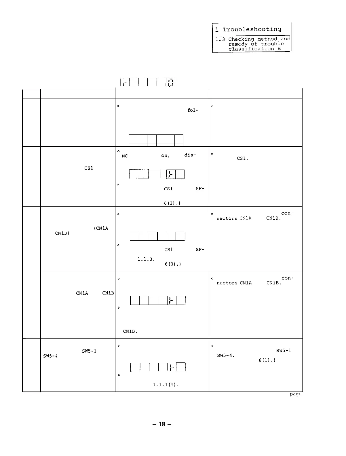
1.3.2 When the power is turned on,
the display on the opera-
tion panel does not indicate
the speed in the status
display mode (as shown in the following figure).
I,-r-rr-rTl
--
Item
Cause
Check
Remedy
When the equipment is
o
While the display on the
D
Turn on the power of the
linked with the NC
operation panel is as
fol-
NC.
through the bus, the
lows,
turn on the NC power
1
power of the NC is not
and check that the display
turned on.
indicates the speed (as shown
in the above figure).
I-
When the equipment is
Even after the power of the
'
EC
is turned
on,
the
dis-
D
Correctly set the rotary
linked with the NC
switch
CSl.
through the bus, the
play on the operation panel
rotary switch
CSl
on the
is as follows.
printed circuit board
2
SF-TL card is not placed
Ill
I
III
I-
in the correct position.
o
Check the position of the
rotary switch
CSl
on the
SF-
TL card by referencing Sec-
tion 3.1.3.
(See Appendix
6t31.1
When the equipment is
o
Even after the power of the
o
Correctly connect the
con-
connected with the NC
NC is turned on, the display
nectars
CNlA
and
CNlB.
through the bus, the bus
on the operation panel is as
cable connectors
(CNlA
follows.
and
CNlB)
on the printed
3
circuit board SF-TL card
I-
i
are not correctly con-
nected.
D
Check the position of the
rotary switch
CSl
on the
SF-
TL card by referencing Refer-
ence
1.1.3.
(See Appendix
6t31.1
When the equipment is
o
Even after the power of the
o
Correctly connect the
con-
linked with the NC
N
C is turned on, the display
nectars
CNlA
and
CNlB.
through the bus, the
on the operation panel is as
connectors
CNlA
and
CNlB
follows.
on the printed circuit
board SF-TL card are nqt
t
I
4
correctly connected.
D
Check the connections by
referencing Appendixes l-6
to l-9.
Especially, check
that a termination resistor
is connected to the connector
CNlB.
All the positions of the
0
Even after the power of the
o
Correctly set the positions
dip switches
SW5-1
to
NC is turned on, the display
of the dip switches
SWS-1
to
SW5-4
on the printed
on the operation panel is as
sw5-4.
circuit board SF-CA
follows.
(See Appendix
6(l).)
5
card are not turned
off.
I
I
I
I
I
II
1-
o
Check the positions of the
switch SW5 by referencing
Reference
1.1.1(l).
Continued on the next
page
-18-

 Loading...