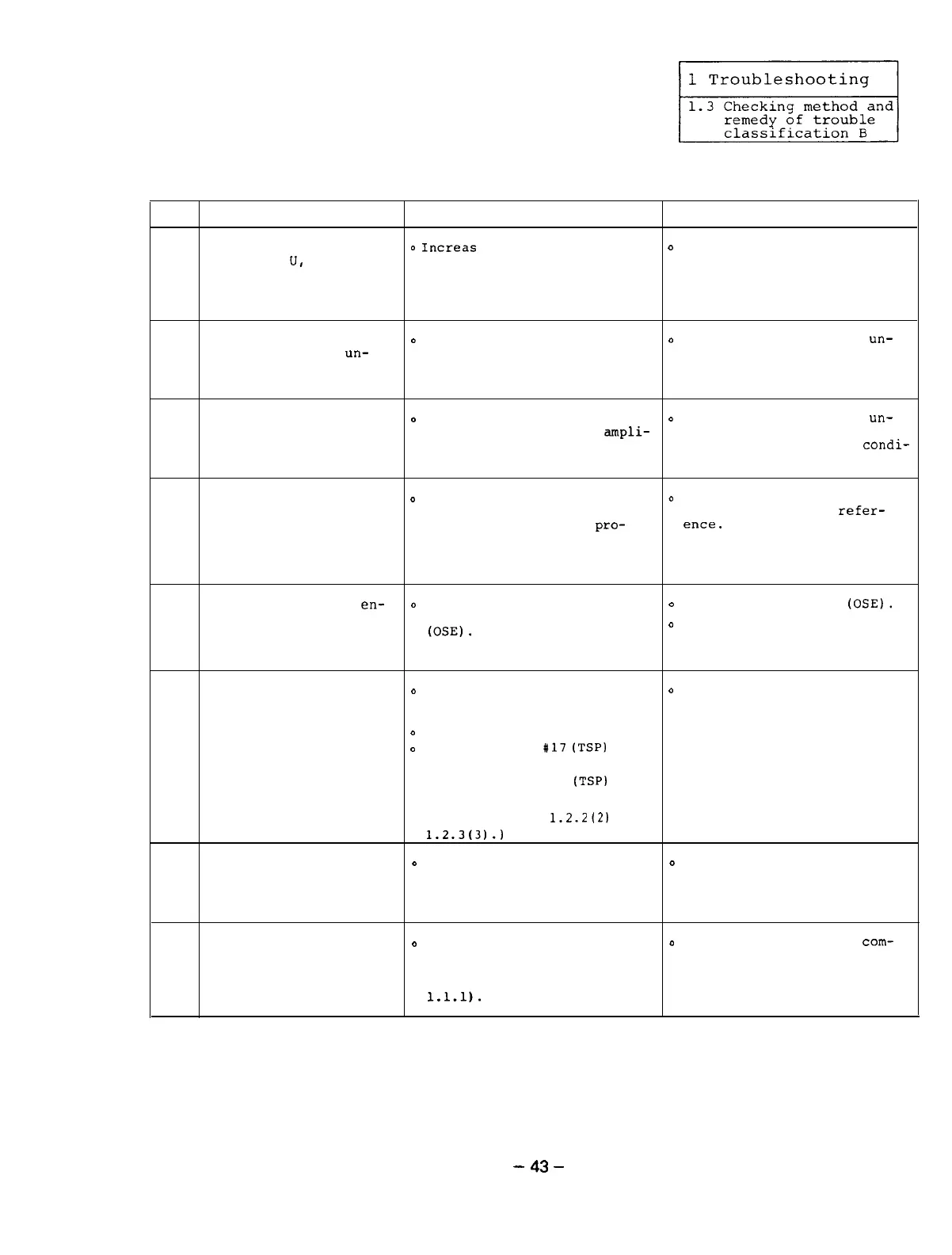
1.3.5 The motor does not rotate at a speed being specified.
Item
Cause Check
Remedy
The phase sequence of
o
Increas
the value of the
o
Match the phase sequence of
the wires
U,
V, and W
speed reference and check
the motor with that of the
1
of the motor are not
that the motor rotates only
amplifier.
matched with that of
at a low speed.
the amplifier.
The output voltage of
o
Measure the voltage between
D
Check the cause of the
un-
2
the amplifier is
un-
any two points of the wires
balanced output voltage and
balance.
U, V, and W of the amplifier
improve the power condition.
using a circuit tester.
The three phases of the
D
Measure the voltage between
o
Check the cause of the
un-
3
input power voltage are
any two points of the
ampli-
balanced input power voltage
unbalance. fier input terminals Xl, X2
and improve the power
condi-
and X3 using a circuit tester. tion.
The external speed
o
Increase the value of the
o
Correctly set the value of
reference is incorrect. speed reference and check
the external speed
refer-
4
that the motor speed
pro-
ence.
portionally increase.
(Between CH46 and AGA of
SF-CA card)
The motor built-in
en-
o
Check the signal waveform by
o
See the alarm No.23
(OSE).
coder is defective.
referencing the alarm No.23
5
(OSE).
D
Replace the encoder or the
printed circuit board with
a new one.
The parameter of the
o
Compare the reference speed
0
Correctly set the parameter
motor maximum speed is with the following maximum
value.
set to a low value. speed being set.
o
Amplifier parameter: X31 (TSP.
6
o
NC parameter:
#17
(TSP)
. . .
9" CRT screen
NC parameter: X49
(TSPl
. . .
14" CRT screen
(See References
1.2.2(2)
and
1.2.3t31.1
The motor is overloaded.
o
Check the load using a load
o
Review the cutting condition
7
meter or the load display in
and tool.
the status display mode
(see Section 1.1.1).
The override command is
o
Check the override command
D
Turn off the override
com-
input.
using the speed display in
mand.
8
the status display mode of
the amplifier (see Section
1.1.1).
-
43
-

 Loading...