1 Troubleshooting
1.3.4
The motor does not rotate.
Item
Cause Check
Remedy
Trouble analysis
0
When a rotation command is
o
Review the cause and take a
issued,
an alarm is indicated
proper action by referencing
on the display on the spindle
Section 1.3.3.
amplifier printed circuit
1
board (SF-CA card).
D
When no alarm occurs:
0
Go to the Item 2 or later.
The control signal cable
o
Check that the cables are
0
Correctly connect them.
or power cable is
in-
correctly connected and
2
correctly connected or
they are not broken.
D
Replace the broken cable
is broken.
with a new one.
The input power voltage
o
Measure the voltages at the
D
Improve the power condition
is abnormal.
input terminals Xl, X2, and so that the input power
3
X3 of the amplifier using a voltage is in the allowable
circuit tester.
range.
(See Table 1.3.)
The control power supply
D
Measure all the DC output
o
Replace the control power
4
(SF-PW module) is
defec-
voltages of the SF-PW module
supply (SF-PW module) with
tive.
using a circuit tester.
a new one.
(See Appendix
6(4).)
(See Section 2.4.1.)
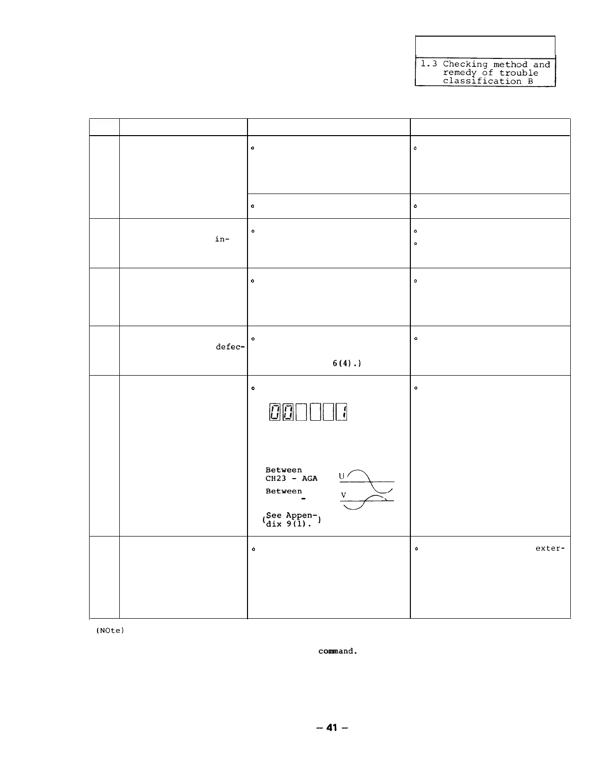
The printed circuit
o
Set the amplifier parameterer
o
Replace the printed circuit
board SF-CA card is as follows,
input a reference
board SF-CA card with a new
defective.
amnrrnn
(Note)
one.
(See Section 2.4.4.)
speed in the open loop state
to cause the motor to rotate,
and check that a reference
sine wave occurs on the
5
oscilloscope.
l%z;:%AGA
U-L
CH14
-
AGA
e
(See
Appen-)
dix
9(l).
The external emergency
o
Check that the bit 2
0
Correctly connect the
exter-
stop signal or reset
(emergency stop) of the
nal signal cable.
signal is input.
external signal is turned on
6
or the portion between CON1
pins No.47 and No.48 (emer-
gency stop) or portion bet-
ween pins No.19 and No.20
(alarm reset) is turned on.
(Note)
The parameter 00 becomes valid just after it is set to 1. Since the parameter is
cleared when the power is turned off or the equipment is reset, just after 1 is set,
input the speed reference and start
coannand.
-41-

 Loading...