2.9
Adjusting and replacing motor built-in encoder
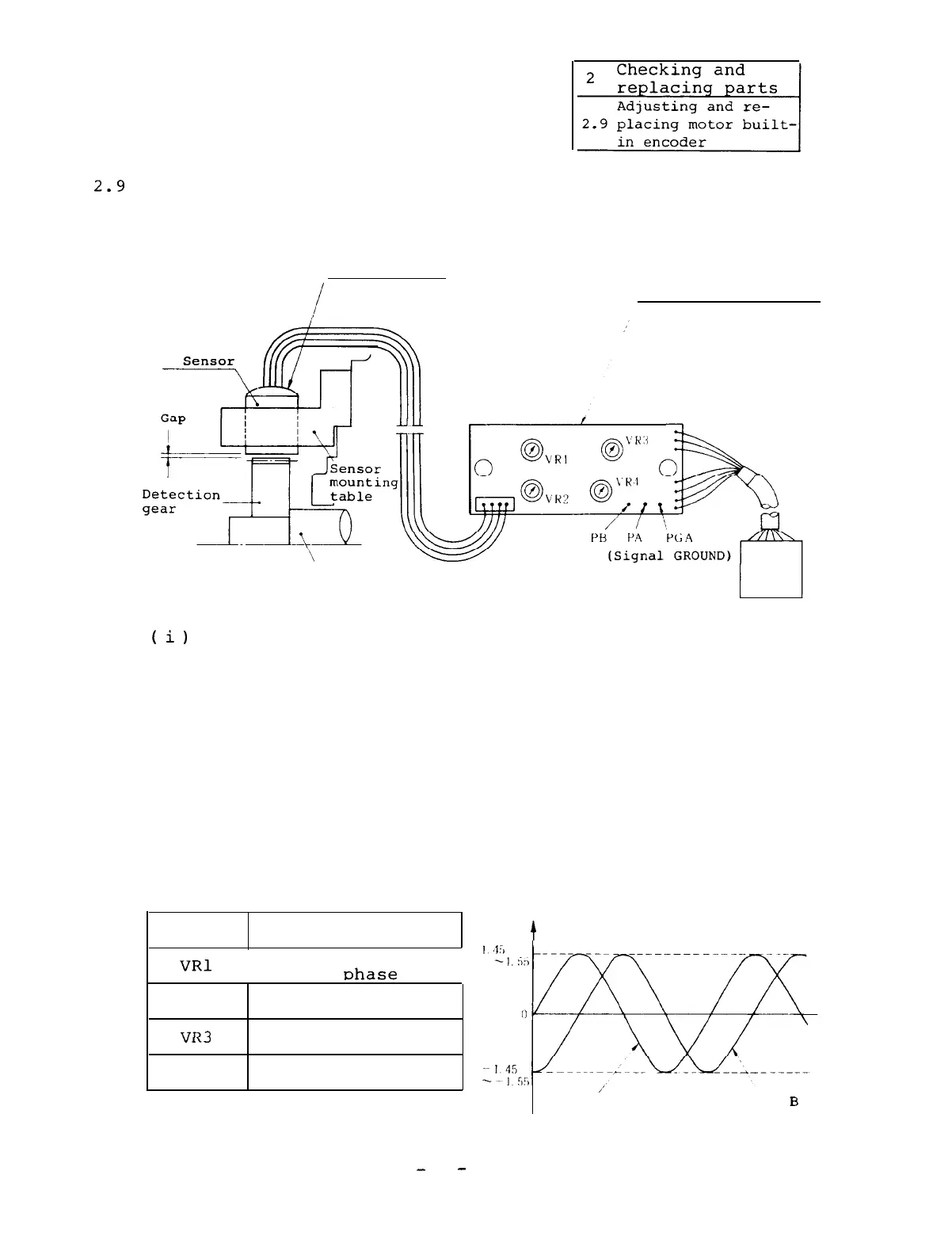
2.9.1 Adjusting printed circuit board
Motor built-in
encoder
Printed circuit board
in motor terminal box
Shaft
(
i)
Observe the waveforms at the same time for phases
A and B at the check pins on the above printed cir-
cuit board using an oscilloscope.
Phase A output . . . . . . Between PA and PGA
Phase B output . . . . . . Between PB and PGA
(ii) Rotate the motor in the forward direction (counter-
clockwise viewed from the shaft end) at a low speed
so that the waveform can be easily observed and
adjust the following four volumes until the follow-
ing output waveforms can be observed.
Volumes
Adjustment
function
VRl
Zero level adjust-
ment of chase A
VR2
Amplitude adjust-
ment of phase A
T7D7
Zero level adjust-
”
1x-I
ment of phase B
VR4
Amplitude adjust-
ment of ohase B
t
Amplitude(V)
,’
Phase A
Phase
B
-
74
-

 Loading...