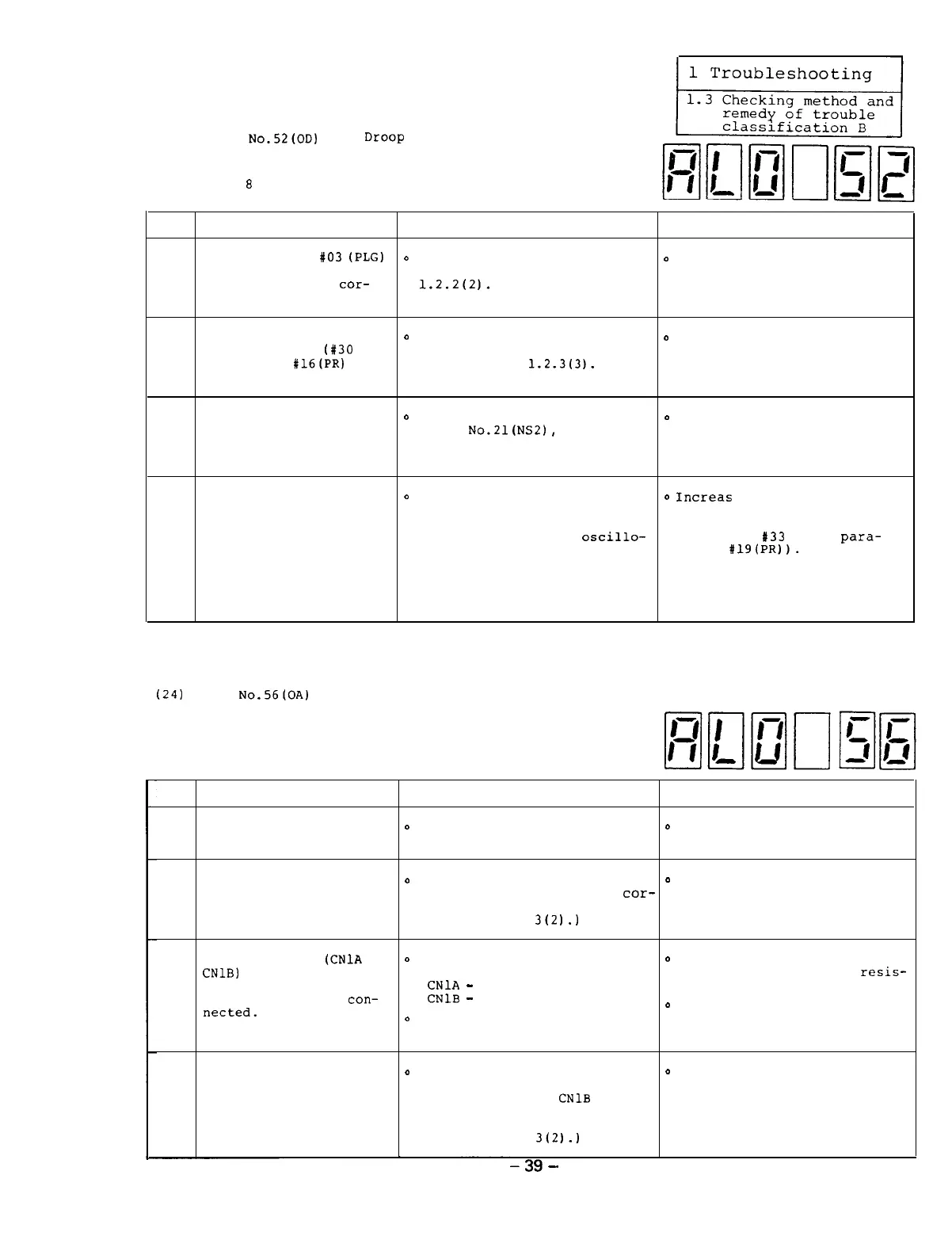
(23) Alarm
N0.52(0D)
Over
Droop
[This alarm occurs when the position error
becomes too large in synchronous tapping mode
(for
8
rotations against the reference value.)]
Item
Cause
Check Remedy
The parameter
#03
(PLG)
D
Check the parameter being set
o
Correctly set the parameter
1
which is set from the
by referencing Reference
value.
amplifier is not
cor-
1.2.2(2).
rectly set.
The bits 8 and E of the
D
Check the parameter being set
o
Correctly set the parameter
2
parameter ORS2
(#30
for
by referencing Reference
values.
amplifier;
#16(~~)
for
1.2.2 (2) and
1.2.3(3).
NC) are not correctly
set.
The orientation encoder
0
In the same manner as the
0
Replace the encoder with a
is defective.
alarm
No.21(NS2),
check the
new one.
3
signal waveform from the en-
coder.
The reference time
0
Measure the acceleration time
o
Increas
the value of the
constant is small.
using a stop watch or observe acceleration time constant
the speed signal terminals parameter CSN (amplifier
SMO and OM using an
oscillo-
parameter
#33
or NC
para-
4
scope and check that the
meter
#19(PR)).
acceleration time is shorter
than the reference constant
time.
(See Appendixes 1-4 and l-5.)
(24)
Alarm
No,56(OA)
Other Axis Fault
Item
Cause
Check
Remedy
1
The servo axis alarm
o
Check that the servo axis
o
Remove the cause of the
occurs.
alarm occurs.
servo axis alarm.
The cable CAM11 which
o
Replace the cable CAM11 and
0
Replace the cable CAM11 with
2
is linked with the NC
check that the equipment
cor-
the new one.
through the bus is rectly works.
defective.
(See Appendix
3(2).)
The connectors
(CNlA
and
o
Visually check the following
o
Correctly connect the CAM11
CNlB)
on the printed
connections.
cable and termination
resis-
3
circuit board SF-TL card
CNlA
-
CAM11 cable
tor in place.
are not correctly
con-
CNlB
-
termination resistor
netted.
0
Tighten the connector screws
0
Check that the connector
screws are loosen.
The termination resistor
o
Replace the termination
0
Replace the termination
is defective.
resistor which is connected
resistor with a new one.
4
to the connector
CNlB
and
check that the equipment cor-
rectly works.
(See Appendix
3(2).)
39
-

 Loading...