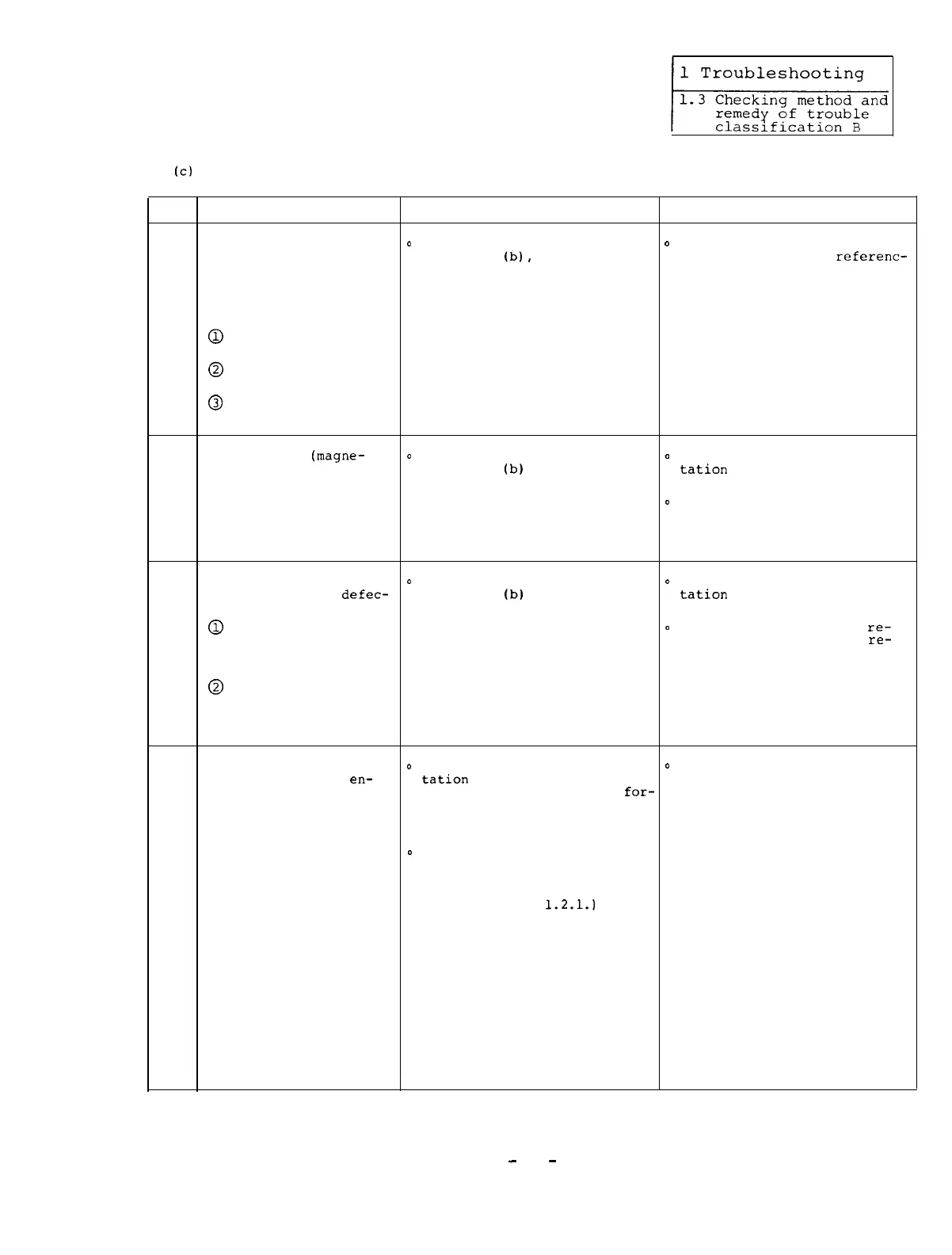
(c)
Although the motor performs the orientation stop,
the stop state is abnormal.
Item
Cause
Check Remedy
The orientation control
o
In the same manner as the
o
Readjust the orientation
circuit is abnormally
Item 1 of
(b),
check that control circuit by
referenc-
set or defective.
the position feedback
ing Section 3.
(Note) The following
signal is normal.
defective situations
1
can be considered.
@
The motor stops with
a hunting.
@
The servo rigidity
is weak.
@
The motor over-
shoots in speed.
The detector
(magne-
o
In the same manner as the
0
Readjust the spindle orien-
sensor or encoder) is
Item 1 of
(b)
above, check
tation
control circuit by
defective.
that the position feedback
referencing Section 3.
2
signal is normal.
0
If it is impossible to re-
adjust such a circuit,
replace the detector with a
new one.
The following printed
o
In the same manner as the
o
Readjust the spindle orien-
circuit board is
defec-
Item 1 of
(b)
above, check
tation
control circuit by
tive.
that the position feedback
referencing Section 3.
0
In case of analog
signal is normal.
0
If it is impossible to
re-
linkage:
adjust such a circuit,
re-
3
SF-OR card or
place the printed circuit
SF-CA card
board with a new one.
@
In case of bus
(See Section 2.4.2 and
linkage:
2.4.3)
SF-TL card or
SF-CA card
The backlash of the
o
In the multiple point orien-
o
Decrease the backlash of the
portion where the
en-
tation
operation, check that
portion where the encoder is
coder is mounted is
the stop position of the
for-
mounted.
large.
ward orientation differs from
that of the reverse orienta-
tion.
o
Set the following address and
data on the amplifier display
in the status display debug
mode.
(See Reference
1.2.1.)
4
Check that the display data
of the forward orientation is
the same as that of the
reverse orientation and there
is no electrical problem. An
example of display data is as
follows.
Continued on the next page.
-
51
-

 Loading...