6 - 19 6 - 19
MELSEC-Q
6 PROGRAMMING
6.5 For Use in Remote I/O Network (Q62AD-DGH)
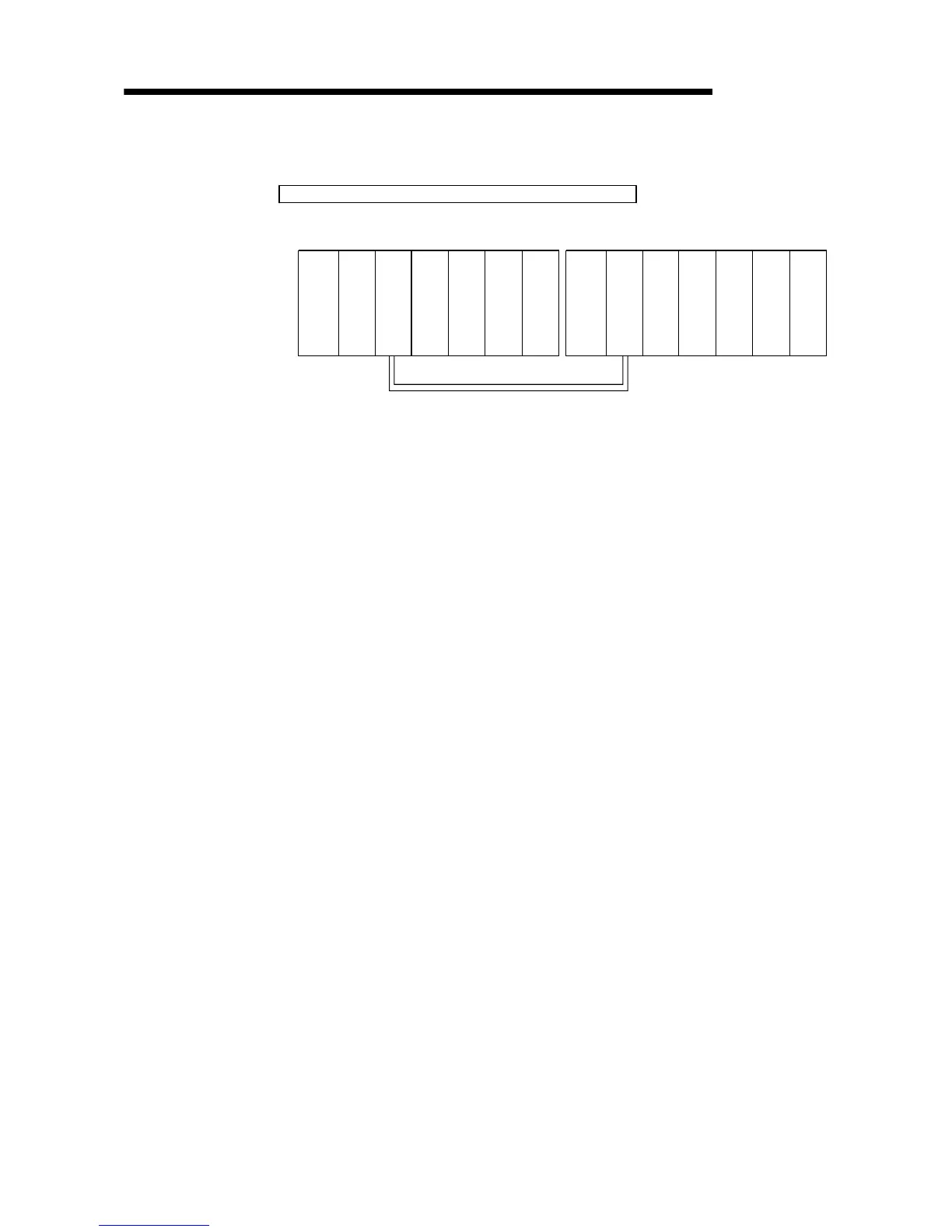
System configuration used in the program explanation
(1) System configuration
Q
n
C
P
U
Q
J
7
1
L
P
2
1
Q
X
1
0
Q
Y
1
0
Q
J
7
1
L
P
2
5
Q
X
1
0
Q
Y
1
0
X/Y100
X/Y10F
X/Y110
X/Y11F
X/Y120
X/Y12F
Q
6
2
A
D
D
G
H
|
Remote master station (Network No. 1)
Remote I/O station (Station No. 1)
to to to
Power
supply
module
Power
supply
module
(2) Program conditions
In this program, the digital output values that have been A/D converted using
CH1 and CH2 of the Q62AD-DGH are read by the CPU of the remote master
station.
CH1 performs sampling processing, and CH2 performs averaging processing
every 50 times. An error code appears in BCD if a write error occurs.
(a) Initial settings
• A/D conversion enable channel.............CH1, CH2
• Count-based
averaging processing channel ..............Average count setting of
CH2: 50 times
• Process alarm channel ..........................Lower lower limit value setting of
CH2: 1000
Lower upper limit value setting
: 1500
Upper lower limit value setting
: 6000
Upper upper limit value setting
: 7000
• Input signal error detection channel ......Setting of CH1: 10%
(b) Devices used by the user
• Initial setting request signal .....................................X20
• Digital output value read command input signal .....X21
• Input signal error detection reset signal ..................X22
• Error reset signal......................................................X23
• Error code display (BCD 3 digits) ............................Y30 to Y3B
• A/D conversion completed flag................................D10
• CH1 digital output value...........................................D1, D2 (W1, W2)
• CH2 digital output value...........................................D3, D4 (W3, W4)
• Warning output flag..................................................D5 (W5)
Process alarm ..........................................................b2, b3 of D5 (M12, M13)
• Input signal error detection flag ...............................D6, M30 (W6, M30)
• Error code.................................................................D7 (W7)
 Loading...


