3 - 19 3 - 19
MELSEC-Q
3 SPECIFICATIONS
3.3 I/O Signals for the PLC CPU
3.3.1 List of I/O signals
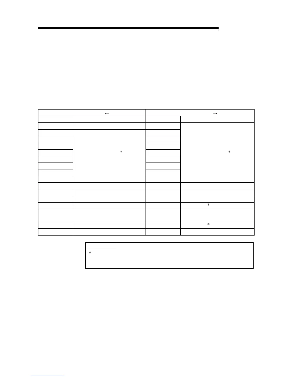
Table 3.4 lists the I/O signals of the Q64AD-GH.
Table 3.5 lists the I/O signals of the Q62AD-DGH.
Note that I/O numbers (X/Y) shown in this chapter and thereafter are the values when
the start I/O number for the A/D converter module is set to 0.
Table 3.4 List of I/O signal (Q64AD-GH)
Signal direction CPU Module Q64AD-GH Signal direction CPU Module Q64AD-GH
Device No. (Input) Signal name Device No. (Output) Signal name
X0 Module ready Y0
X1 Y1
X2 Y2
X3 Y3
X4 Y4
X5 Y5
X6 Y6
X7
Use prohibited
1
Y7
X8 Warning output signal Y8
Use prohibited
1
X9 Operating condition setting completed flag Y9 Operating condition setting request
XA Offset/gain setting mode flag YA User range writing request
XB Channel change completed flag YB Channel change request
XC Input signal error detection signal YC
Use prohibited
1
XD
Maximum value/minimum value reset
completed flag
YD
Maximum value/minimum value reset
request
XE A/D conversion completed flag YE
Use prohibited
1
XF Error flag YF Error clear request
POINT
1 These signals cannot be used by the user since they are for system use only.
If these are turned ON/OFF by the sequence program, the functioning of the
A/D converter module cannot be guaranteed.
 Loading...


