3 - 42 3 - 42
MELSEC-Q
3 SPECIFICATIONS
3.4.12 Input signal error detection/warning output settings (buffer memory address 47:
Un\G47)
(1) This area is used to set whether the input signal error detection/process alarm/rate
alarm warning will be output or stopped on a channel basis.
(2) To make the input signal error detection/warning output settings valid, the
operating condition setting request (Y9) must be turned ON/OFF. (Refer to
Section 3.3.2.)
(3) By default, all channels are set to disable.
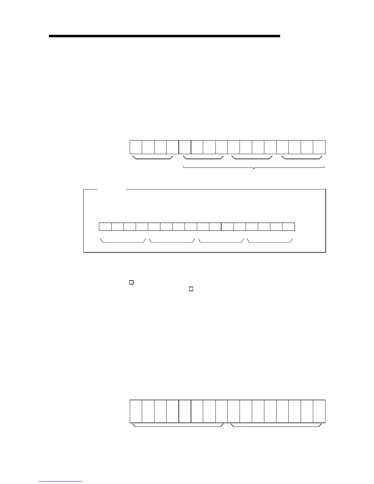
b15 b14 b13 b12 b11 b10 b9 b8 b7 b6 b5 b4 b3 b2 b1 b0
CH4 CH3 CH2 CH10 0 0 0 CH4 CH3 CH2 CH1CH4 CH3 CH2 CH1
Information of b12
to b15 is fixed at 0.
Input signal error detection Rate alarm setting Process alarm setting
0: Enable, 1: Disable
For Q62AD-DGH, information of b2, b3, b6, b7, b10 and b11 is fixed at 0.
Example
When channel 1 is enabled for process alarm warning output and channel 3 is enabled for
input signal error detection, 0BFEH
(3070) is stored into the buffer memory address 47
(Un\G47).
b15
CH4 CH3 CH2 CH1
EB0
0BFE
H
(3070)0000101111111110
b14b13b12b11b10b9b8b7b6b5b4b3b2b1b0
F
CH4 CH3 CH2 CH1CH4 CH3 CH2 CH1
3.4.13 Warning output flag (buffer memory address 48 :Un\G48)
(1) If the digital output value or its varying rate falls outside the setting range set to the
CH
process alarm upper/lower limit value (buffer memory addresses 86 to 117:
Un\G86 to Un\G117) or CH
rate alarm upper/lower limit value (buffer memory
addresses 122 to 137: Un\G122 to Un\G137), the warning output flag for the
corresponding channel turns to 1.
(2) For both the process alarm and rate alarm, whether the warning is for the upper or
lower limit value can be checked on a channel basis.
(3) When the digital output value or its varying rate returns to within the setting range,
the warning output flag is automatically reset.
(4) If the warning is detected on any one of the channels enabled for A/D conversion
and enabled for process alarm or rate alarm warning output, the Warning output
signal (X8) also turns ON.
(5) When the operating condition setting request (Y9) is turned ON, the warning
output flag is cleared.
b15 b14 b13 b12 b11 b10 b9 b8 b7 b6 b5 b4 b3 b2 b1 b0
CH2 CH2 CH1 CH1CH4 CH4 CH3 CH3CH2 CH2 CH1 CH1CH4 CH4 CH3 CH3
Lower
limit
value
Upper
limit
value
Lower
limit
value
Upper
limit
value
Lower
limit
value
Upper
limit
value
Lower
limit
value
Upper
limit
value
Lower
limit
value
Upper
limit
value
Lower
limit
value
Upper
limit
value
Lower
limit
value
Upper
limit
value
Lower
limit
value
Upper
limit
value
Rate alarm Process alarm
0: Normal, 1: Alarm ON
For Q62AD-DGH, information of b4 to b7 and b12 to b15 is fixed at 0.
 Loading...


