3 - 28 3 - 28
MELSEC-Q
3 SPECIFICATIONS
3.4 Buffer Memory
3.4.1 Buffer memory assignment
This section describes the buffer memory assignments of the A/D converter modules.
(1) Buffer memory assignment of Q64AD-GH
Table 3.6 Buffer memory assignment of Q64AD-GH (1/5)
Address
Hexadecimal Decimal
Description Default R/W
1
0
H
0 A/D conversion enable/disable setting 0000
H
R/W
2
1
H
1
CH1 Average time/Average number of times/Move average
/Time constant settings
0R/W
2
2
H
2
CH2 Average time/Average number of times/Move average/
Time constant settings
0R/W
2
3
H
3
CH3 Average time/Average number of times/Move average/
Time constant settings
0R/W
2
4
H
4
CH4 Average time/Average number of times/Move average/
Time constant settings
0R/W
2
5
H
5
to to
8
H
8
System area — —
9
H
9 Averaging process specification 0 R/W
2
A
H
10 A/D conversion completed flag 0 R
B
H
11 CH1 Digital output value(16Bit) 0 R
C
H
12 CH2 Digital output value(16Bit) 0 R
D
H
13 CH3 Digital output value(16Bit) 0 R
E
H
14 CH4 Digital output value(16Bit) 0 R
F
H
15
to to
12
H
18
System area — —
13
H
19 Error code 0 R
14
H
20 Setting range 0 R
15
H
21 System area — —
16
H
22 Offset/gain setting mode offset specification 0 R/W
17
H
23 Offset/gain setting mode gain specification 0 R/W
18
H
24
to to
1D
H
29
System area — —
1E
H
30 CH1 Maximum value(16Bit) 0 R/W
2
1F
H
31 CH1 Minimum value(16Bit) 0 R/W
2
20
H
32 CH2 Maximum value(16Bit) 0 R/W
2
21
H
33 CH2 Minimum value(16Bit) 0 R/W
2
1 Indicates whether reading and writing to/from a sequence program are enabled.
R : Read enabled
W : Write enabled
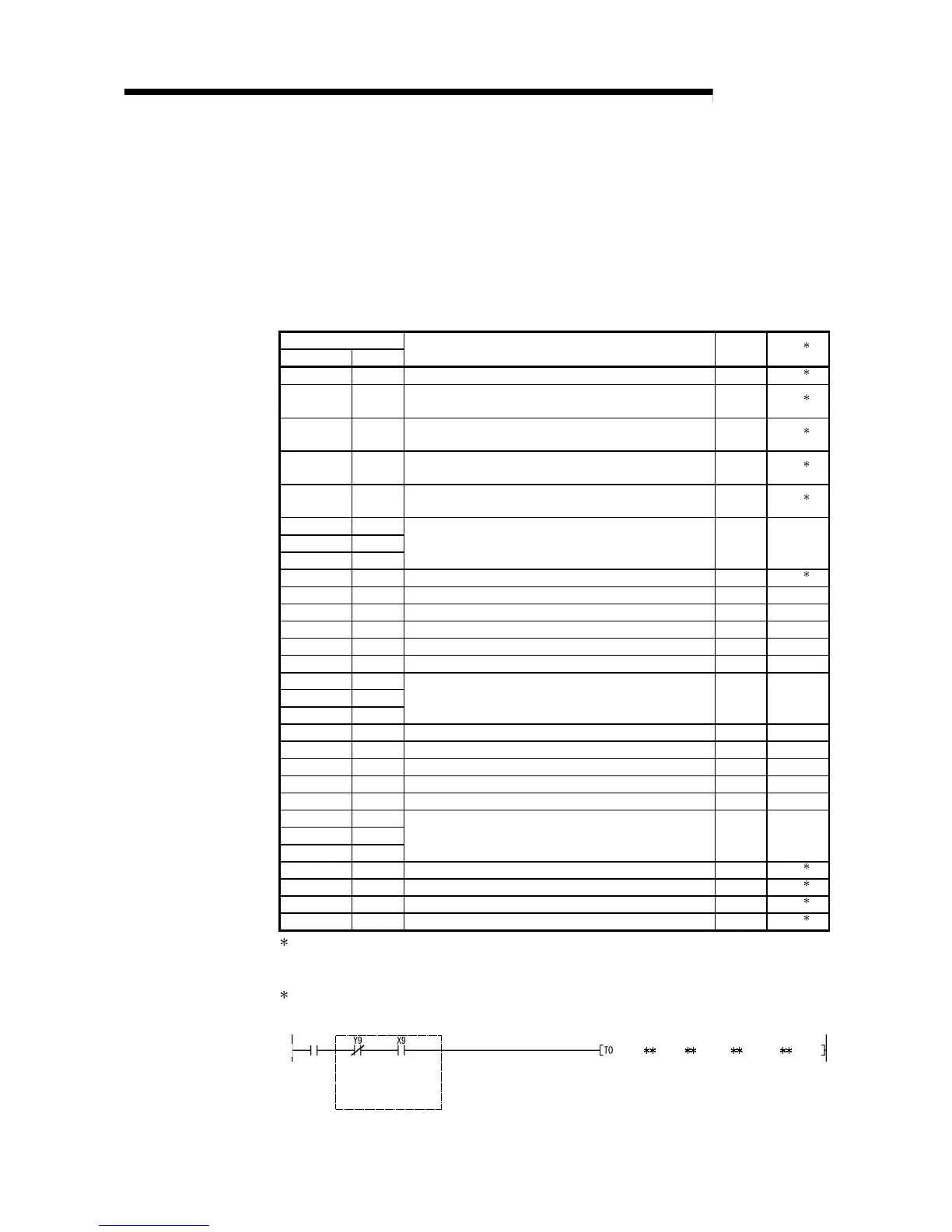
2 When writing data to the buffer memory, always perform write under the interlock conditions (buffer
memory write conditions) of the following I/O signals.
Writing
request
Buffer memory writing conditions
Operating
condition
setting
request
Operating
condition
setting
completed
flag
 Loading...


