3 - 29 3 - 29
MELSEC-Q
3 SPECIFICATIONS
Table 3.6 Buffer memory assignment of Q64AD-GH (2/5)
Address
Hexadecimal Decimal
Description Default R/W
1
22
H
34 CH3 Maximum value(16Bit) 0 R/W
2
23
H
35 CH3 Minimum value(16Bit) 0 R/W
2
24
H
36 CH4 Maximum value(16Bit) 0 R/W
2
25
H
37 CH4 Minimum value(16Bit) 0 R/W
2
26
H
38
to to
2E
H
46
System area — —
2F
H
47 Input signal error detection/warning output settings 0FFF
H
R/W
2
30
H
48 Warning output flag 0 R
31
H
49 Input signal error detection flag 0 R
32
H
50
to to
35
H
53
System area — —
36
H
54
37
H
55
CH1 Digital output value(32Bit) (L)
(H)
0R
38
H
56
39
H
57
CH2 Digital output value(32Bit) (L)
(H)
0R
3A
H
58
3B
H
59
CH3 Digital output value(32Bit) (L)
(H)
0R
3C
H
60
3D
H
61
CH4 Digital output value(32Bit) (L)
(H)
0R
3E
H
62
3F
H
63
CH1 Maximum value(32Bit) (L)
(H)
0R/W
2
40
H
64
41
H
65
CH1 Minimum value(32Bit) (L)
(H)
0R/W
2
42
H
66
43
H
67
CH2 Maximum value(32Bit) (L)
(H)
0R/W
2
44
H
68
45
H
69
CH2 Minimum value(32Bit) (L)
(H)
0R/W
2
46
H
70
47
H
71
CH3 Maximum value(32Bit) (L)
(H)
0R/W
2
48
H
72
49
H
73
CH3 Minimum value(32Bit) (L)
(H)
0R/W
2
4A
H
74
4B
H
75
CH4 Maximum value(32Bit) (L)
(H)
0R/W
2
4C
H
76
4D
H
77
CH4 Minimum value(32Bit) (L)
(H)
0R/W
2
4E
H
78
to to
55
H
85
System area — —
1 Indicates whether reading and writing to/from a sequence program are enabled.
R : Read enabled
W : Write enabled
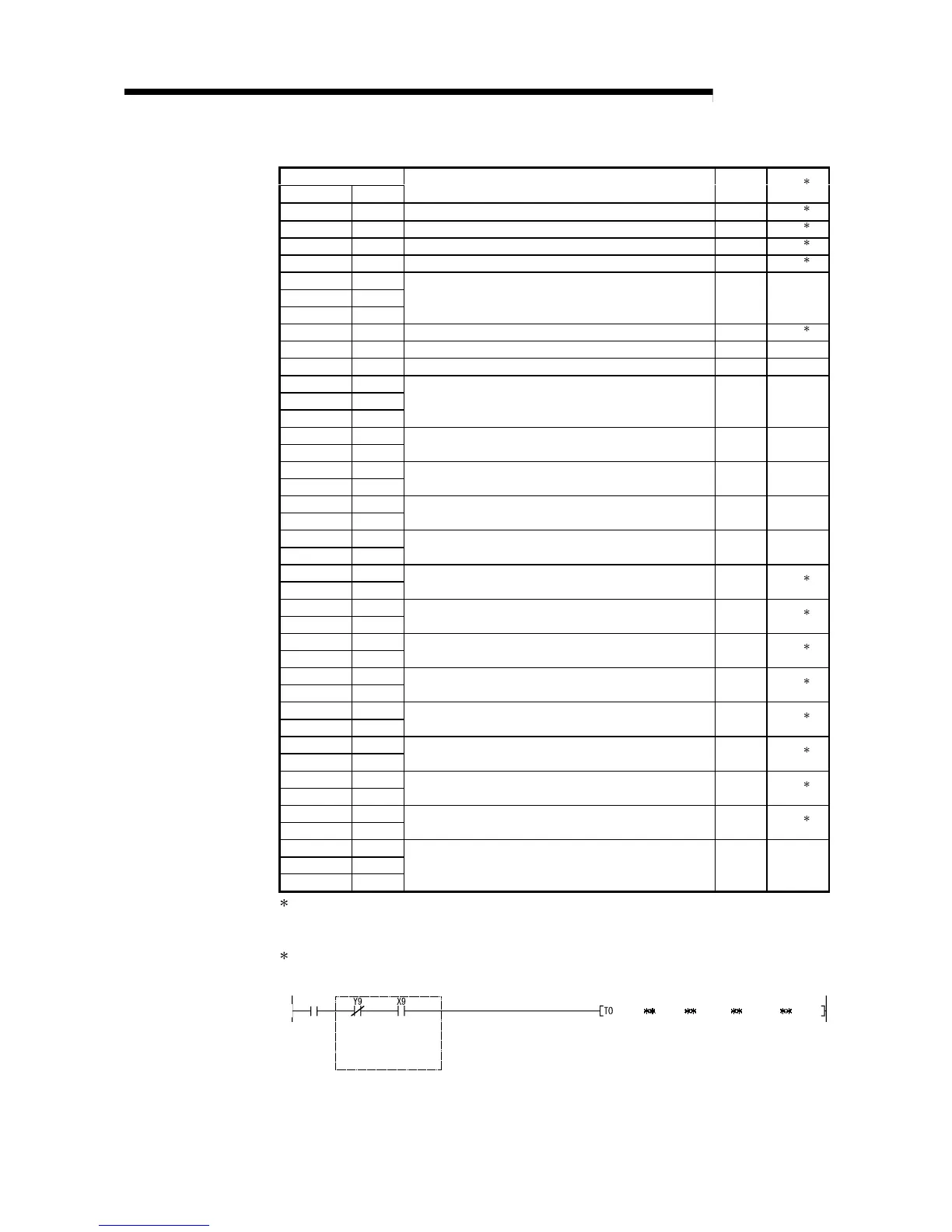
2 When writing data to the buffer memory, always perform write under the interlock conditions (buffer
memory write conditions) of the following I/O signals.
Writing
request
Buffer memory writing conditions
Operating
condition
setting
request
Operating
condition
setting
completed
flag
 Loading...


