3 - 31 3 - 31
MELSEC-Q
3 SPECIFICATIONS
Table 3.6 Buffer memory assignment of Q64AD-GH (4/5)
Address
Hexadecimal Decimal
Description Default R/W
1
7E
H
126
7F
H
127
CH2 Rate alarm upper limit value (L)
(H)
0R/W
2
80
H
128
81
H
129
CH2 Rate alarm lower limit value (L)
(H)
0R/W
2
82
H
130
83
H
131
CH3 Rate alarm upper limit value (L)
(H)
0R/W
2
84
H
132
85
H
133
CH3 Rate alarm lower limit value (L)
(H)
0R/W
2
86
H
134
87
H
135
CH4 Rate alarm upper limit value (L)
(H)
0R/W
2
88
H
136
89
H
137
CH4 Rate alarm lower limit value (L)
(H)
0R/W
2
8A
H
138 CH1 Input signal error detection setting value 50 R/W
2
8B
H
139 CH2 Input signal error detection setting value 50 R/W
2
8C
H
140 CH3 Input signal error detection setting value 50 R/W
2
8D
H
141 CH4 Input signal error detection setting value 50 R/W
2
8E
H
142
to to
9D
H
157
System area — —
9E
H
158
9F
H
159
Mode switching setting 0 R/W
2
A0
H
160
to to
C7
H
199
System area — —
C8
H
200 Pass data classification setting
3
0R/W
2
C9
H
201 System area — —
CA
H
202
CB
H
203
CH1 Industrial shipment settings offset value
3
(L)
(H)
0R/W
2
CC
H
204
CD
H
205
CH1 Industrial shipment settings gain value
3
(L)
(H)
0R/W
2
CE
H
206
CF
H
207
CH2 Industrial shipment settings offset value
3
(L)
(H)
0R/W
2
D0
H
208
D1
H
209
CH2 Industrial shipment settings gain value
3
(L)
(H)
0R/W
2
D2
H
210
D3
H
211
CH3 Industrial shipment settings offset value
3
(L)
(H)
0R/W
2
D4
H
212
D5
H
213
CH3 Industrial shipment settings gain value
3
(L)
(H)
0R/W
2
D6
H
214
D7
H
215
CH4 Industrial shipment settings offset value
3
(L)
(H)
0R/W
2
D8
H
216
D9
H
217
CH4 Industrial shipment settings gain value
3
(L)
(H)
0R/W
2
1 Indicates whether reading and writing to/from a sequence program are enabled.
R : Read enabled
W : Write enabled
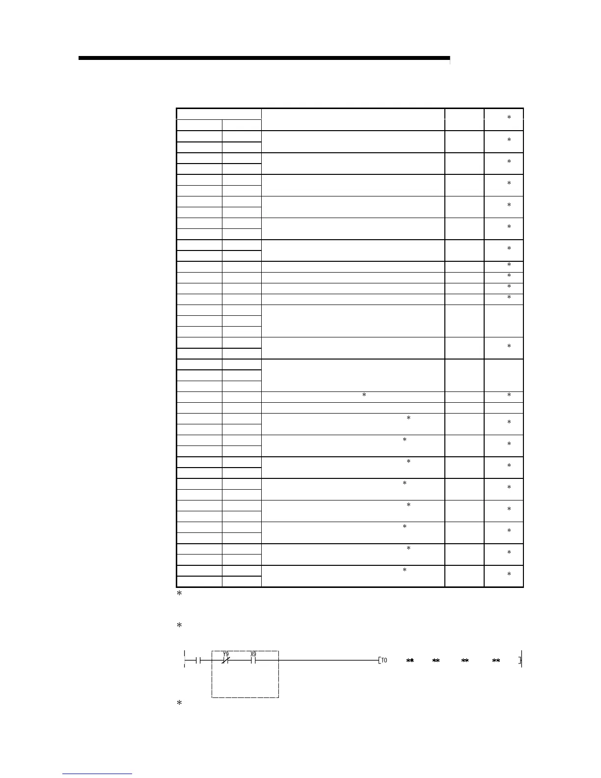
2 When writing data to the buffer memory, always perform write under the interlock conditions (buffer
memory write conditions) of the following I/O signals.
Writing
request
Buffer memory writing conditions
Operating
condition
setting
request
Operating
condition
setting
completed
flag
3 Areas used to restore the user range settings offset/gain values when online module change is made.
Refer to chapter 7 for details of online module change.
 Loading...


