3Controller
Outside dimensions/Installation dimensions
3-47
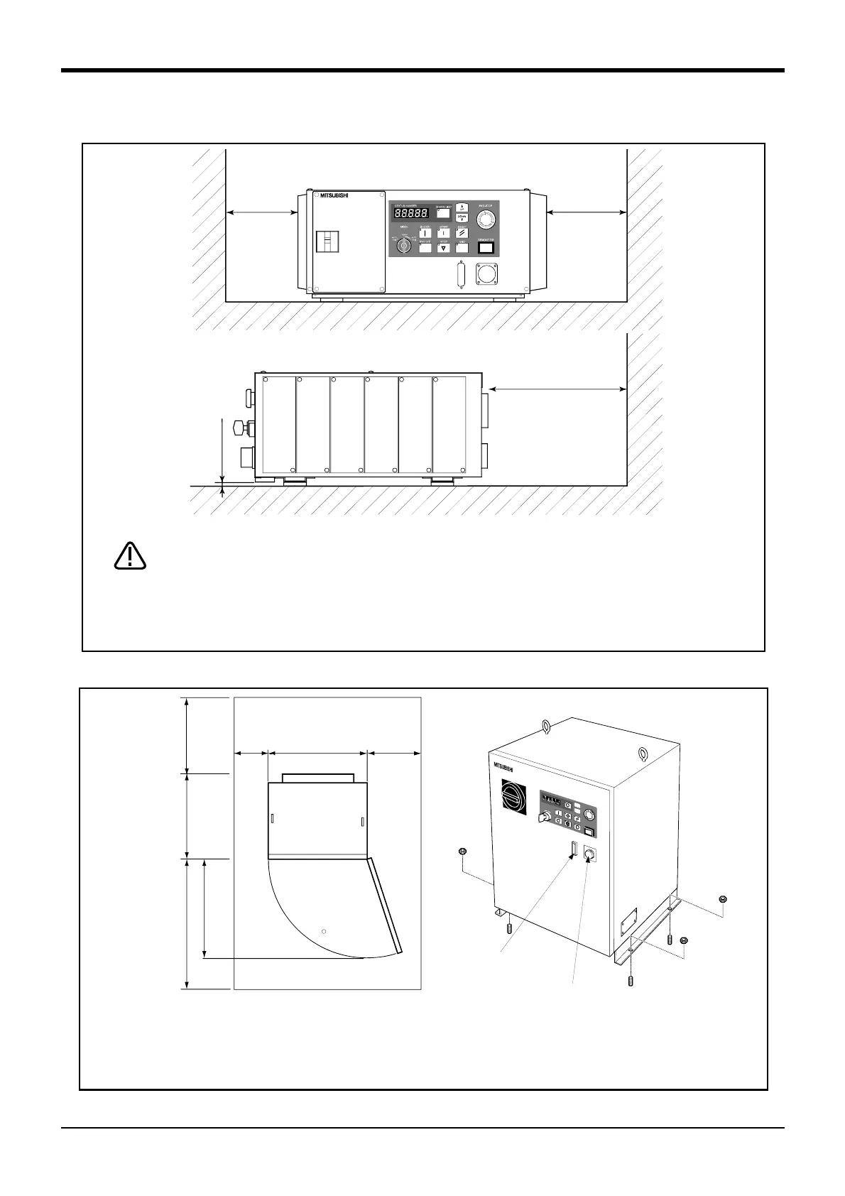
3.3.2 Installation dimensions
Fig.3-7 : Installation of controller (CR2B-574 controller)
Fig.3-8 : Installation of controller (CR3-535M controller)
150
150
250
or more
7 or more
Horizontal placement
Use the rubber foot (4 positions) at the bottom of the controller as it is, or put the
spacer, and leave the space between the installation side and the controller
installation side more than 7mm when you fix the controller with the installation
screw.In the other case, the air intake hole at the bottom of the controller is
occupied, and temperature rises in the board, and causes the trouble.
CAUTION
<CR3-535M>
S
V
O
O
F
F
S
T
O
P
E
N
D
S
V
O
O
N
M
O
D
E
T
E
A
C
H
A
U
T
O
(
E
x
t
.
)
A
U
T
O
(
O
p
.
)
S
T
A
R
T
R
E
S
E
T
D
O
W
N
U
P
S
T
A
T
U
S
N
U
M
B
E
R
R
E
M
O
V
E
T
/
B
E
M
G
.
S
T
O
P
C
H
A
N
G
D
I
S
P
(Anchor bolt installation: 4 places)
The mold cover
for the RS-232C connector
The rubber cover
for the T/B connector
450
1
1
0
440
450
Back
Approx. 500
Front
Approx. 500
Maintenance area
Controller
(upside)
Side
Approx.
300
Side
Approx.
200
(View from upside)
Note1)
Note1) The controller sucks in the outside air and discharges the inside air after cooling (Fig. 3-4).
The space required for cooling is 100 mm minimum. Reserve approximately 500 mm of space
behind the unit as the maintenance work area.

 Loading...


