3Controller
Emergency stop input/output
3-53
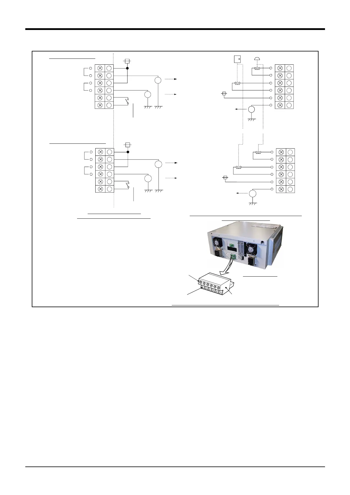
Fig.3-11 : Connection of the external emergency stop (CR2B-574 controller)
[Note] Refer to Page 109, "6.1.7 Examples of safety measures" together, and carry out wiring to the emergency stop.
RG (24G)
24V
EMG.
STOP
DOOR
Switch
RA5
1
2
3
4
5
6
RA1
RA2
RA3
Emergency stop input
Emergency stop output
Door switch input
RG (24G)
Short piece 1
24V
1
2
3
4
5
6
Note1)
Upside terminal block
Short piece 2
System emergency
stop line
(Prepared by cusotmer)
RG (24G)
24V
EMG.
STOP
DOOR
Switch
1
2
3
4
5
6
RA51
RA11
RA31
RG (24G)
24V
1
2
3
4
5
6
RA21
Bottom side terminal block
①
②
③
④
⑤
⑥
Controller rear side
Emergency stop input
Door switch input
Short piece 1
Short piece 2
Emergency stop output
Note1)
System emergency
stop line
(Prepared by cusotmer)
Wire fixing screw
Wire insert
Maker:Phoenix Contact
Type:FRONT-MSTB2.5/6-ST-5.08
(Customer-prepared wiring)
(Controller side)
EXTEMG connector
Same for both top and bottom outputs
Internal circuit composition of
external emergency stop and door switch
Example of wiring for external emergency stop and door switc
(customer-prepared wiring)
Note 1)
Emergency stop output opens
when either one of the emergency stop switches
shown below or an input signal turns on.
・
Emergency stop switch of the controller.
・
Emergency stop switch of the T/B (option).
・
External emergency stop input.
・
External door input.
・
The T/B mount/dismount switch is OFF
when the T/B is unconnected.

 Loading...


