3-62
Parallel input/output unit
3Controller
・The signals assigned as dedicated inputs can be used as general-purpose inputs during program execution. Note
that for safety proposes, these should not be shared with the general-purpose inputs other than for numeric
value inputs. The signals assigned as dedicated outputs cannot be used in the program. An alarm will occur dur
-
ing operation if used.
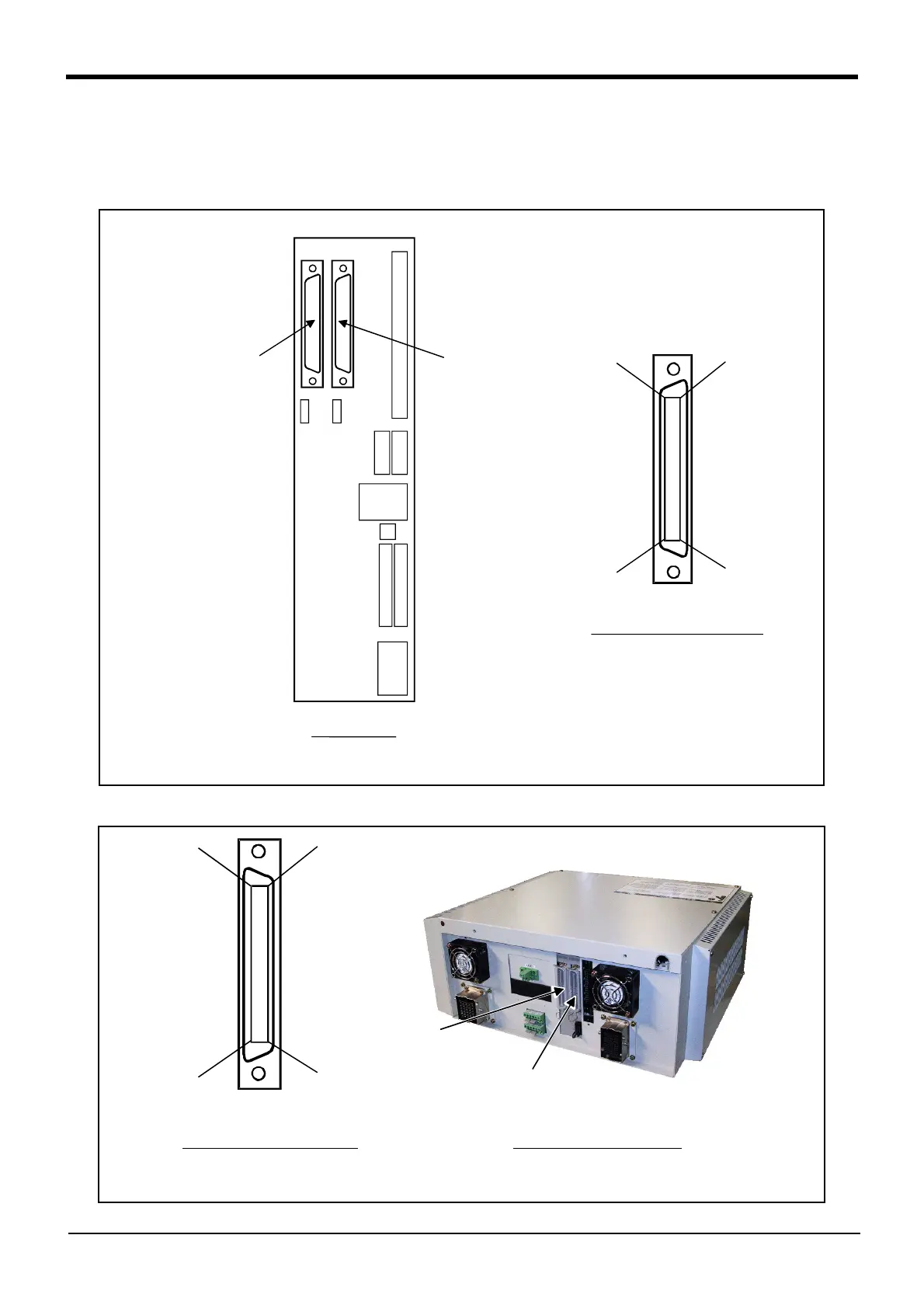
Fig.3-19 : Parallel input/output unit (in the control unit) connection and pin layout (CR3-535M controller)
Fig.3-20 : Parallel input/output unit (in the control unit) connection and pin layout (CR2B-574 controller)
50
1
25
26
<CN100>
<CN300>
Input 16 to 31
Output 16 to 31
Input 0 to 15
Output 0 to 15
(Channel No. is set to 0 at shipment)
Connection and pin layout
Control unit
*The I/O card in the control unit is equal to the PIO unit of the option.
(Occupies one channel)
[*1]
50
1
25
26
<CN300>
<CN100>
Connector pin layout
Input 0 to 15
Output 0 to 15
Input 16 to 31
Output 16 to 31
Controller back side
*The I/O card in the control unit is equal to the PIO unit of the option.
(Input 32/Output 32 points)

 Loading...


