577
DATE-, DATE-P
1
2
3
4
4
6
7
8
7.15 Clock instructions
7.15.4 DATE-, DATE-P
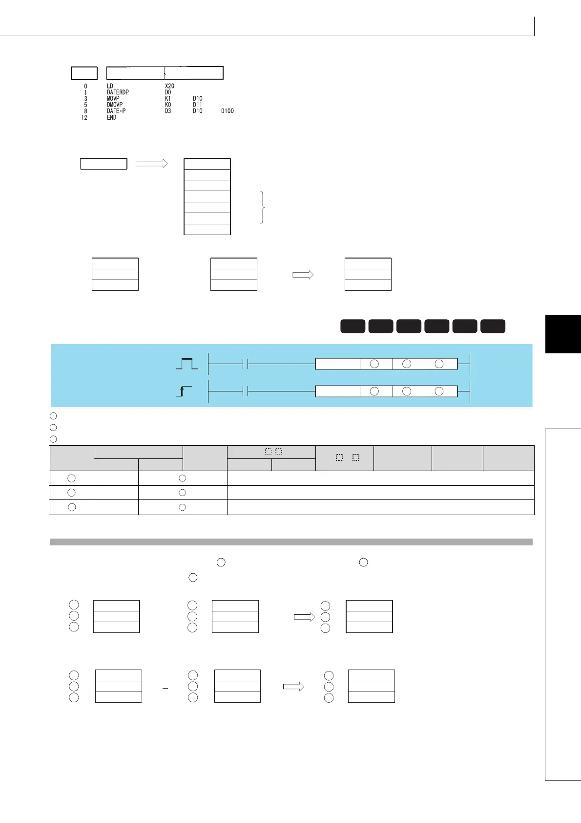
[List Mode]
[Operation]
• Time data read operation triggered by DATERDP instruction.
• Addition triggered by DATE+P instruction.
: Head number of the devices where the clock time data to be adjusted by substraction is stored (BIN 16 bits)
: Head number of the devices where time data to be subtracted for adjustment is stored (BIN 16 bits)
: Head number of the devices where the result of subtraction of clock (time) data will be stored (BIN 16 bits)
Function
(1) Subtracts the time data designated by from the clock data designated by , and stores the result into the area starting
from the device designated by .
For example, if the clock time 3:50:10 were subtracted from the clock time 10:40:20, the operation would be performed
as follows:
7.15.4 DATE-, DATE-P Clock data subtraction operation
7.15.4
DATE-, DATE-P
Setting
Data
Internal Devices
R, ZR
J\
U\G
Zn Constants Other
Bit Word Bit Word
–– ––
–– ––
–– ––
Step Instruction Device
Clock element
95
5
15
D1
D2
Year
Day
Month
10
23
41
2
D0
D3
D4
D5
D6
Hour
Minute
Second
Day of week
Time data
H
our: 1
Minute: 0
Second: 0
D11
D12
Hour: 11
Minute: 23
Second: 41
D101
D102
Hour: 10
Minute: 23
Second: 41
D4
D5
+
D100D10D3
Basic
Process
High
performance
Redundant
Universal
LCPU
Command
DATE-
DATE-P
DATE-
Command
DATE-P
S1 S2
D
S1 S2
D
S1
S2
D
S1
S2
D
S2
S1
D
Data rangeData range Data rang
Hour
Minute
Second
+1
+2
(0 to 23)
(0 to 59)
(0 to 59)
Hour
Minute
Second
+1
+2
(0 to 23)
(0 to 59)
(0 to 59)
Hour
Minute
Second
+1
+2
(0 to 23)
(0 to 59)
(0 to 59)
S1
S2
D
D
D
S2
S2
S1
S1
Hour: 3
Minute: 50
Second: 10
+1
+2
Hour: 6
Minute: 50
Second: 10
+1
+2
Hour: 10
Minute: 40
Second: 20
+1
+2
S1
S1
S1
D
D
D
S2
S2
S2

 Loading...

