4. STARTUP
4 - 19
4.4.6 Trouble at start-up
CAUTION
Never adjust or change the parameter values extremely as it will make unstable
movement.
POINT
Using the optional MR Configurator2, you can refer to reason for rotation failure,
etc.
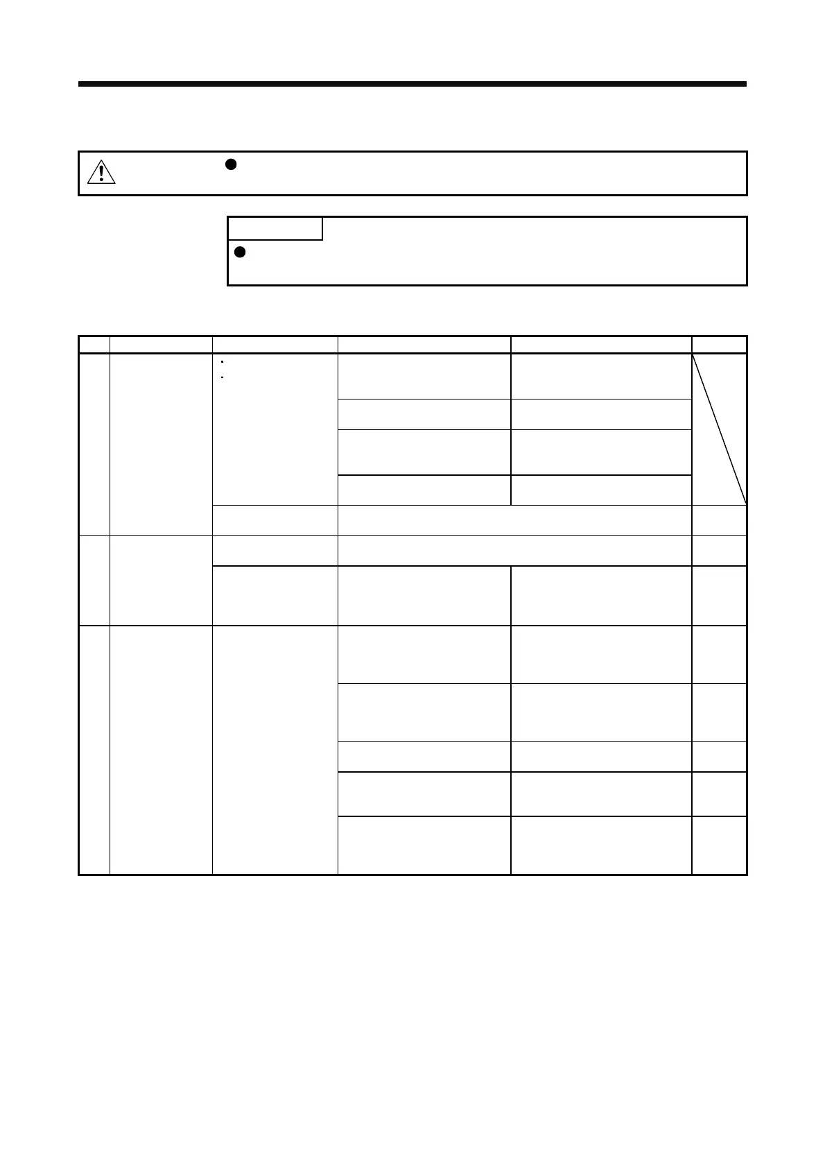
The following faults may occur at start-up. If any of such faults occurs, take the corresponding action.
No.
Start-up sequence Fault Investigation Possible cause Reference
Not improved even if CN1, CN2,
and CN3 connectors are
disconnected.
1. Power supply voltage fault
2. The servo amplifier is
malfunctioning.
Improved when CN1 connector is
disconnected.
Power supply of CN1 cabling is
shorted.
Improved when CN2 connector is
disconnected.
1. Power supply of encoder
cabling is shorted.
2. Encoder is malfunctioning.
1
Power on
LED is not lit.
LED flickers.
Improved when CN3 connector is
disconnected.
Power supply of CN3 cabling is
shorted.
Alarm occurs. Refer to chapter 8 and remove cause. Chapter 8
(Note)
2
Alarm occurs. Refer to chapter 8 and remove cause. Chapter 8
(Note)
Switch on SON
(Servo-on).
(Servo motor shaft is
free.)
Call the external I/O signal
display (section 4.5.7) and check
the on/off status of the input
signal.
1. SON (Servo-on) is not input.
(wiring mistake)
2. 24 V DC power is not supplied
to DICOM.
Section
4.5.7
Call the status display (section
4.5.3) and check the input
voltage of TC (Analog torque
command).
Analog torque command is 0 V. Section
4.5.3
Call the external I/O signal
display (section 4.5.7) and check
the on/off status of the input
signal.
RS1 and RS2 are off. Section
4.5.7
Check the internal speed limit 1
to 7 ([Pr. PC05] to [Pr. PC11]).
Set value is 0. Section
5.2.3
Check the analog torque
command maximum output ([Pr.
PC13]) value.
Torque command level is too low
as compared to the load torque.
Section
5.2.3
3
Switch on RS1
(Forward rotation
start) or RS2
(Reverse rotation
start).
Servo motor does not
rotate.
Check the forward rotation
torque limit ([Pr. PA11]) and the
reverse rotation torque limit ([Pr.
PA12]).
Set value is 0. Section
5.2.1
Note. Only a list of alarms and warnings is listed in chapter 8. Refer to "MELSERVO-J4 Servo Amplifier Instruction Manual
(Troubleshooting)" for details of alarms and warnings.
 Loading...
