5. PARAMETERS
5 - 34
Control
mode
No./symbol/
name
Setting
digit
Function
Initial
value
[unit]
P S T
PB60
PG1B
Model loop
gain after
gain
switching
Set the model loop gain when the gain switching is enabled.
When you set a value less than 1.0 rad/s, the value will be the same as [Pr. PB07].
This parameter will be enabled only when the following conditions are fulfilled.
"Gain adjustment mode selection" in [Pr. PA08] is "Manual mode (_ _ _ 3)".
"Gain switching selection" in [Pr. PB26] is "Input device (gain switching (CDP)) (_
_ _ 1)".
Switching during driving may cause a shock. Be sure to switch them after the servo
motor or linear servo motor stops.
Setting range: 0.0 to 2000.0
0.0
[rad/s]
5.2.3 Extension setting parameters ([Pr. PC_ _ ])
Control
mode
No./symbol/
name
Setting
digit
Function
Initial
value
[unit]
P S T
PC01
STA
Acceleration
time constant
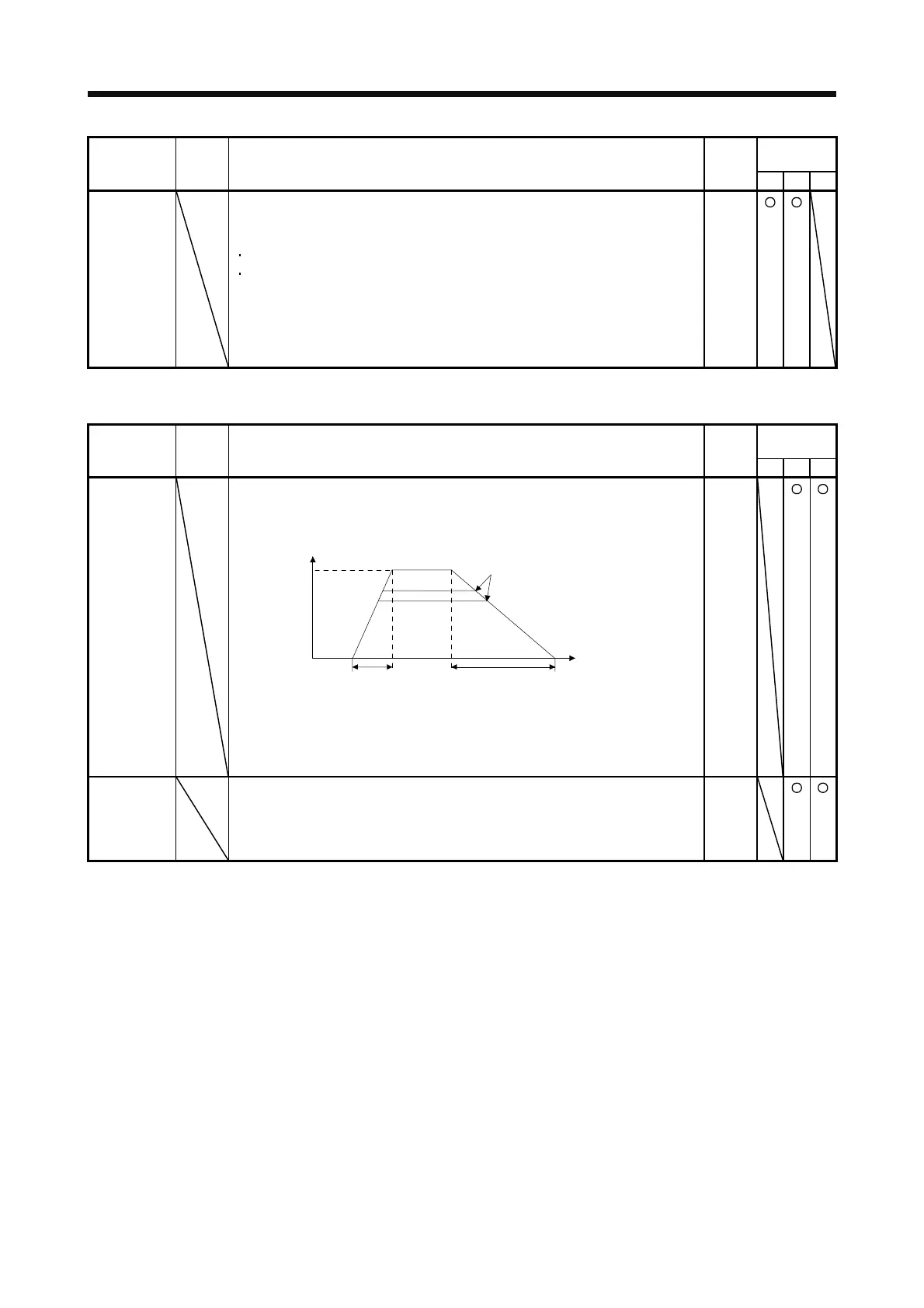
Set the acceleration time required to reach the rated speed from 0 r/min or 0 mm/s
for VC (Analog speed command) and [Pr. PC05 Internal speed command 1] to [Pr.
PC11 Internal speed command 7].
If the preset speed command is lowe
than the rated speed, acceleration/
deceleration time will be shorter.
Time
[Pr. PC02] setting
0 r/min
Rated
speed
Speed
[Pr. PC01] setting
(0 mm/s)
For example for the servo motor of 3000 r/min rated speed, set 3000 (3s) to increase
the speed from 0 r/min to 1000 r/min in 1 second.
Setting range: 0 to 50000
0
[ms]
PC02
STB
Deceleration
time constant
Set the deceleration time required to reach 0 r/min or 0 mm/s from the rated speed
for VC (Analog speed command) and [Pr. PC05 Internal speed command 1] to [Pr.
PC11 Internal speed command 7].
Setting range: 0 to 50000
0
[ms]
 Loading...
