4. STARTUP
4 - 21
4.5.2 Display flowchart
Press the "MODE" button once to shift to the next display mode. Refer to section 4.5.3 and later for the
description of the corresponding display mode.
To refer to and set the gain/filter parameters, extension setting parameters and I/O setting parameters,
enable them with [Pr. PA19 Parameter writing inhibit].
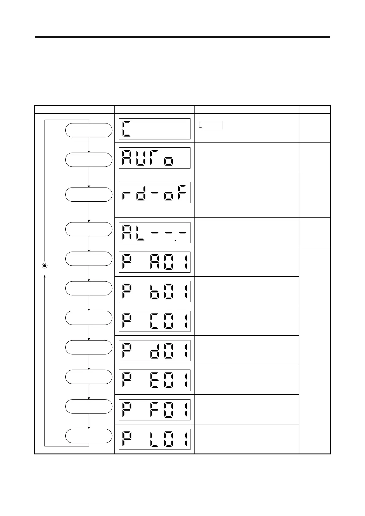
Display mode transition Initial screen Function Reference
Servo status display.
appears at power-on.
(Note)
Section
4.5.3
One-touch tuning
Select this when performing the one-touch
tuning.
Section 6.2
Sequence display, external signal display,
output signal (DO) forced output, test
operation, software version display, VC
automatic offset, servo motor series ID
display, servo motor type ID display, servo
motor encoder ID display, drive recorder
enabled/disabled display.
Section
4.5.4
Current alarm display, alarm history display,
parameter error number display.
Section
4.5.5
Display and setting of basic setting
parameters.
Section
4.5.6
Display and setting of gain/filter parameters.
Display and setting of extension setting
parameters.
Display and setting of I/O setting parameters.
Display and setting of extension setting 2
parameters.
Display and setting of extension setting 3
parameters.
Status display
Diagnosis
Alarms
Basic setting
parameters
Gain/filter
parameters
Extension setting
parameters
Extension setting 2
parameters
Extension setting 3
parameters
I/O setting
parameters
Button
MODE
One-touch tuning
Linear/DD motor
setting parameter
Display and setting of linear/DD motor setting
parameters.
Note. When the axis name is set to the servo amplifier using MR Configurator2, the axis name is displayed and the servo status is then
displayed.
 Loading...
