3. SIGNALS AND WIRING
3 - 21
Symbol
Connection target
(application)
Description
U/V/W
Servo motor
power output
Connect the servo amplifier power output (U, V, and W) to the servo motor power input (U, V,
and W) directly. Do not let a magnetic contactor, etc. intervene. Otherwise, it may cause a
malfunction.
N-
Power regeneration
converter
Power regeneration
common converter
Brake unit
This terminal is used for a power regeneration converter, power regeneration common
converter and brake unit.
Refer to section 11.3 to 11.5 for details.
Protective earth (PE)
Connect it to the grounding terminal of the servo motor and to the protective earth (PE) of the
cabinet for grounding.
3.3.2 Power-on sequence
POINT
The voltage of analog monitor output, output signal, etc. may be unstable at
power-on.
(1) Power-on procedure
1) Always use a magnetic contactor for the main circuit power supply wiring (3-phase: L1, L2, and
L3, 1-phase: L1 and L3) as shown in above section 3.1. Configure up an external sequence to
switch off the magnetic contactor as soon as an alarm occurs.
2) Switch on the control circuit power supply (L11 and L21) simultaneously with the main circuit
power supply or before switching on the main circuit power supply. If the main circuit power
supply is not on, the display shows the corresponding warning. However, by switching on the
main circuit power supply, the warning disappears and the servo amplifier will operate properly.
3) The servo amplifier receives the SON (Servo-on) 2.5 s to 3.5 s after the main circuit power supply
is switched on. Therefore, when SON (Servo-on) is switched on simultaneously with the main
circuit power supply, the base circuit will switch on in about 2.5 s to 3.5 s, and the RD (Ready) will
switch on in further about 5 ms, making the servo amplifier ready to operate. (Refer to (2) of this
section.)
4) When RES (Reset) is switched on, the base circuit is shut off and the servo motor shaft coasts.
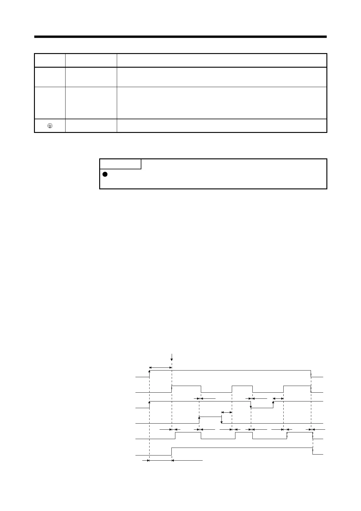
(2) Timing chart
95 ms
95 ms
RD (Ready)
RES (Reset)
SON (Servo-on)
OFF
ON
OFF
ON
ON
OFF
Base circuit
OFF
ON
power supply
OFF
ON
10 ms
5 ms
10 ms
10 ms
5 ms
10 ms
5 ms
10 ms
(2.5 s to 3.5 s)
SON (Servo-on) accepted
Main circuit
Control circuit
Alarm (OFF)
No alarm (ON)
ALM
(Malfunction)
2.5 s to 3.5 s
(Note)
Note. The time will be longer during the magnetic pole detection of a linear servo motor and direct drive motor.
 Loading...
