16. USING A DIRECT DRIVE MOTOR
16 - 15
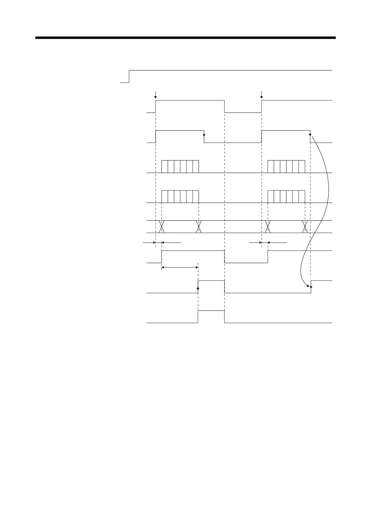
Timing chart at power on under the condition of performing magnetic pole detection
OFF
ON
Power
OFF
ON
SON (Servo-on)
OFF
ON
OFF
ON
BSR (ABS request)
OFF
ON
BST
(ABS transmission data ready)
BSB0
(ABS transmission data bit 0)
BSB1
(ABS transmission data bit 1)
OFF
ON
Base circuit
OFF
ON
RD (Ready)
Operation
possible
Operation
possible
95 ms
95 ms
Absolute
position data
Absolute
position data
During ABS transfer During ABS transfer
BSM (ABS transfer mode)
(Note 1)
(Note 1)
(Note 1)
(Note 1)
(Note 1)
(Note 1)
Warning
Second or later servo-on
First servo-on after power on
15 s or less
Magnetic pole detection time
(Note 2)
Existent
Non-existent
Note 1. Refer to section 12.8.2 (1) (b) for details.
2. Performing the magnetic pole detection triggers [AL. 93 ABS data transfer warning].
For transferring absolute position data to the controller, refer to section 12.8.
16.5 Characteristics
16.5.1 Overload protection characteristics
An electronic thermal is built in the servo amplifier to protect the servo amplifier, the direct drive motor, and
direct drive motor power wires from overloads.
[AL. 50 Overload 1] occurs if overload operation performed is above the electronic thermal protection curve
shown in fig. 16.2. [AL. 51 Overload 2] occurs if the maximum current is applied continuously for several
seconds due to machine collision, etc. Use the equipment on the left-side area of the continuous or broken
line in the graph.
For the system where the unbalanced torque occurs, such as a vertical axis system, it is recommended that
the unbalanced torque of the machine be kept at 70% or less of the motor's rated torque.
This servo amplifier has solid-state direct drive motor overload protection for each axis. (The direct drive
motor overload current (full load current) is set on the basis of 120% rated current of the servo amplifier.)
 Loading...
