APPENDIX
App. - 44
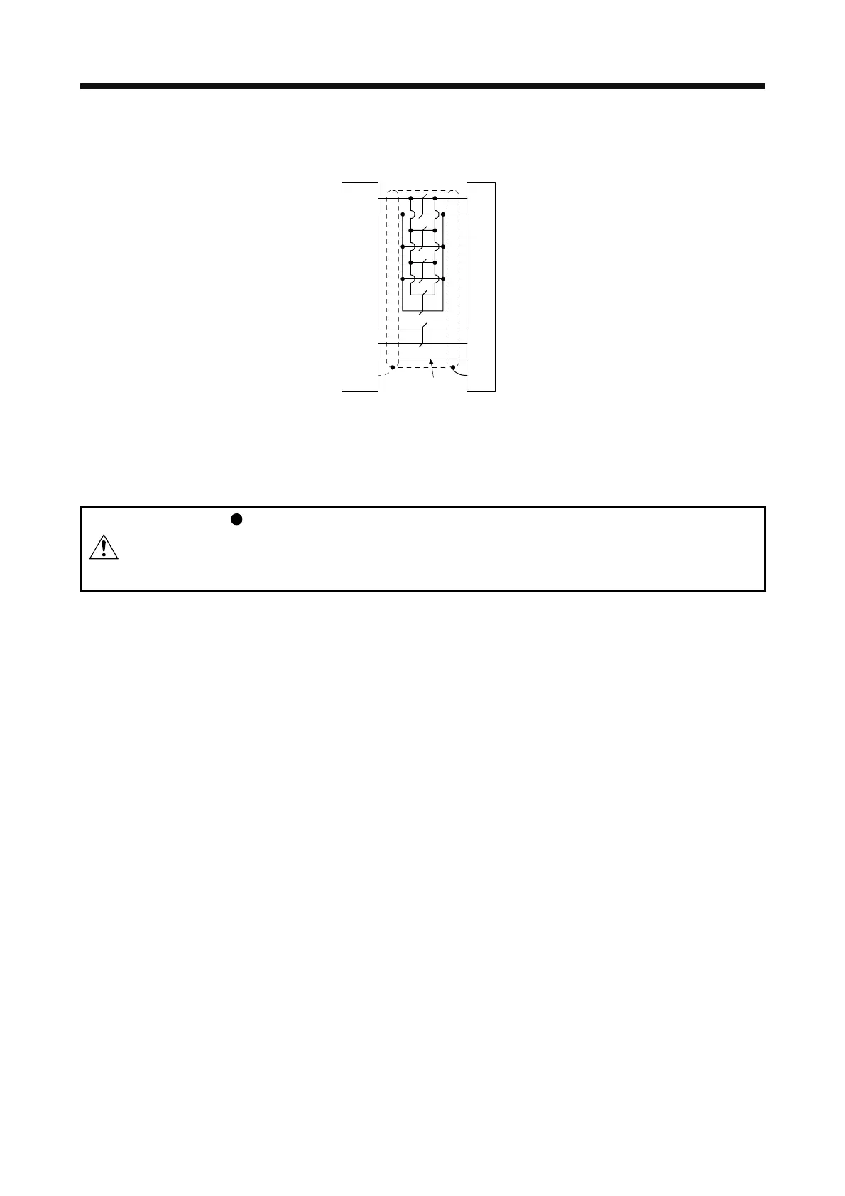
App. 8.3 Internal wiring diagram
(Note)
P5
LG
1
2
MR
MRR
3
4
3
7
9
SD
Plate
1
2
8
9
LG
MR
MRR
SHD
P5
BATBAT
Servo amplifier-side
connector
Servo motor-side
connector
Note. Always make connection for use in an absolute position detection system. Wiring is
not necessary for use in an incremental system.
App. 9 How to replace servo amplifier without magnetic pole detection
CAUTION
Be sure to write the magnetic pole information of the servo amplifier before the
replacement to the servo amplifier after the replacement. If the information before
and after replacement are not the same, the servo motor may operate
unexpectedly.
When replacing the servo amplifier, carry out the magnetic pole detection again. If the magnetic pole
detection cannot be performed unavoidably, write the magnetic pole information from the servo amplifier
before the replacement to the one after the replacement using MR Configurator2.
(1) Procedures
(a) Read the magnetic pole information of the servo amplifier before the replacement.
(b) Write the read magnetic pole information to the servo amplifier after the replacement.
(c) Perform the test operation with the torque limit for ensuring the safety, and confirm that there is no
trouble.
(2) Migration method of the magnetic pole information
(a) How to read the magnetic pole information from the servo amplifier before the replacement
1) Open the project in MR Configurator2, select "MR-J4-A" for model, and select "Linear" for
operation mode.
2) Check that the personal computer is connected with the servo amplifier, and select "Diagnosis"
and then "Linear diagnosis".
 Loading...
