8 - 53
8. DEBUGGING FUNCTION
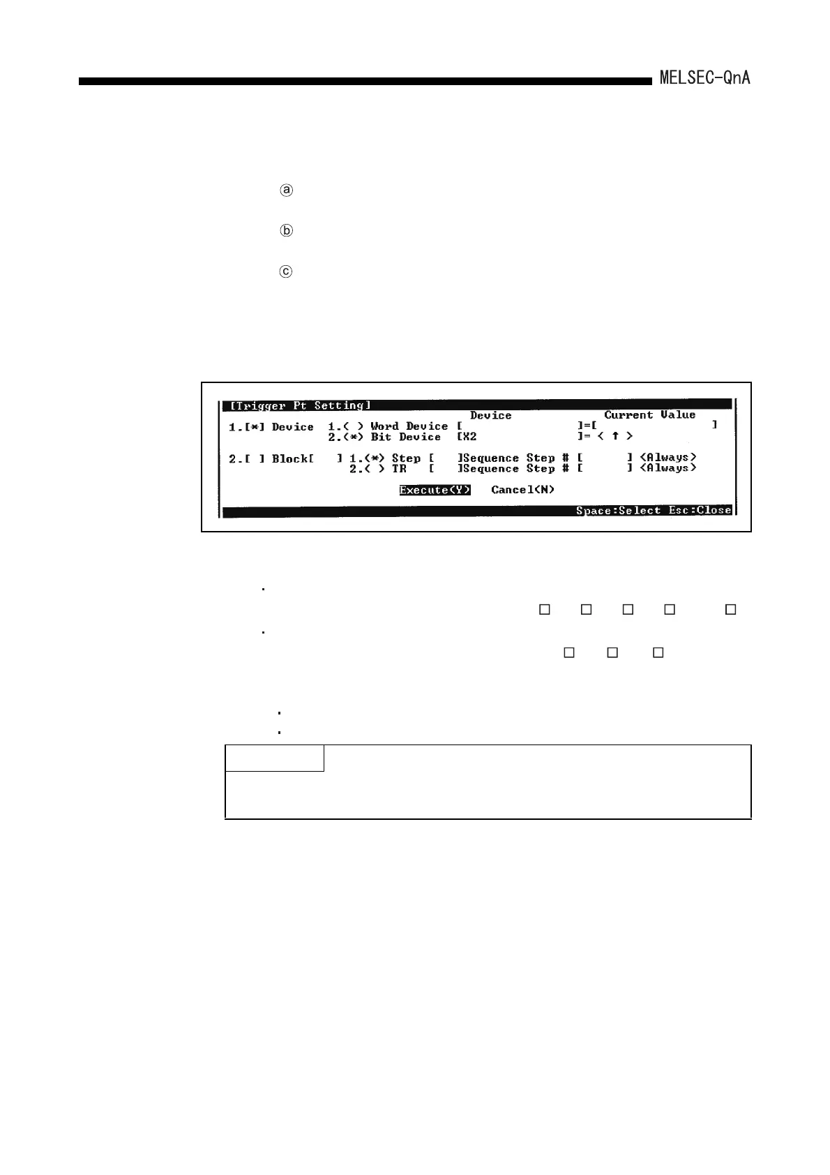
3) "Trigger Point"
Set the point at which the trigger is executed. Select one of the following:
The following shows the setting device under the detailed condition.
The following qualifications are possible with respect to the devices listed
above.
Digit designation for bit devices
Bit number designation for word devices
Upon execution of
each instruction
: When executing PTRA instruction
At Request of PDI : When operating trigger using the peripheral devices
capable of GPP function.
Specify Detail
Condition
: Set a device and step number.
The following shows setting examples: The details
on how to make the settings and trigger execution
timing are the same as described in Section 8.2
Monitor condition setup in Monitor function.
Bit device : X, FX, Y, FY, M, L, F, SM, V, B, SB, T (Contact), ST
(Contact), C (Contact), J \X, J \Y, J \B, J \SB, BL \S
Word device : T (Current value), ST (Current value), C (Current value), D,
SD, FD, W, SW, R, Z, ZR, U \G, J \W, J \SW
POINT
The trace execution time, program name, step and branch factor are automatically
added to the trace results.
 Loading...

