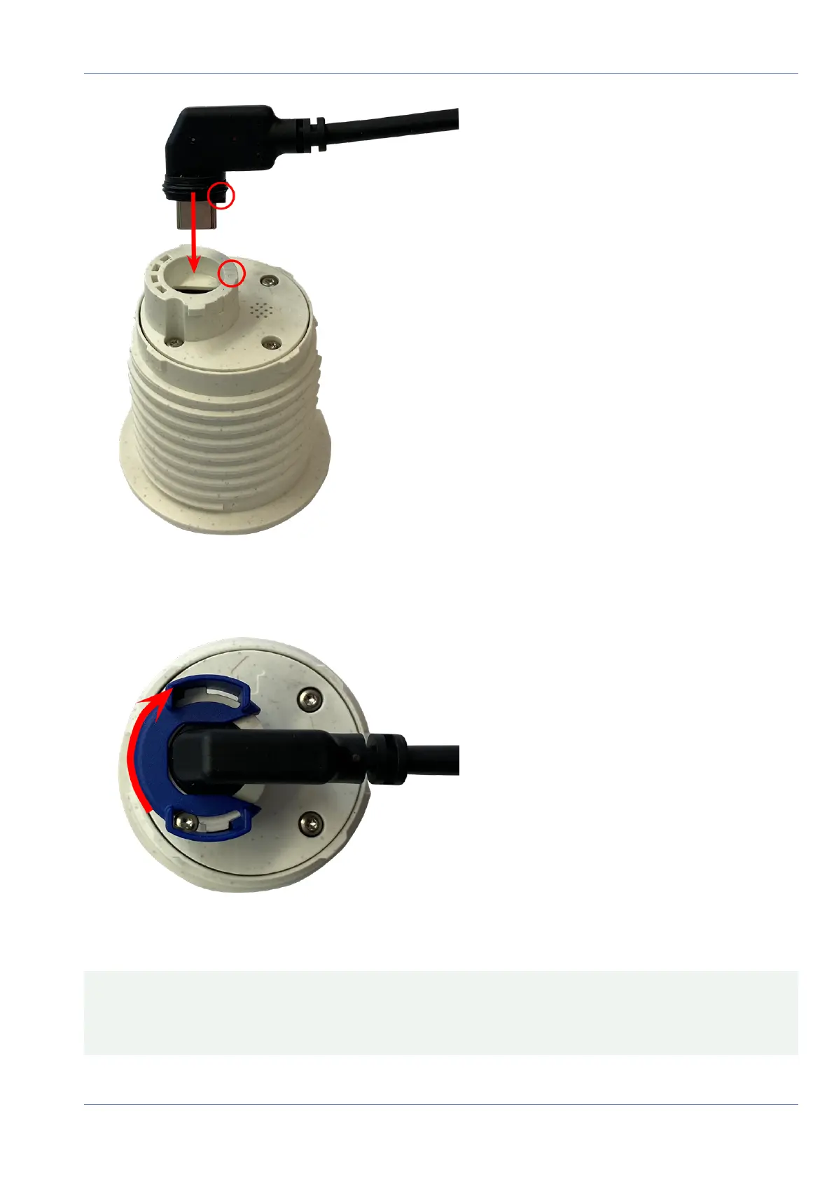
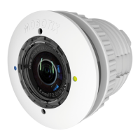
Fig. 27: Connect the sensor module cable
5. Lock sensor module cable: Apply the blue bayonet catch onto the connector of the sensor module as
shown and turn it clockwise until it gently snaps shut.
Fig. 28: Lock sensor module cable
6. Repeat steps 3 to 6 for the remaining sensor modules or the blind module 1.5, respectively.
CAUTION! The sensor modules are not yet protected against theft and unwanted rotation (e.g., due to vibra-
tion). It is thus highly recommended to install the security clips M.4. Proceed as outlined in Installing the
Security Clips, p. 46.
Proceed with Closing the Module Housing, p. 47.
Mounting
Installing a Thermal Front Plate
58 / 110