62
EN
B CLASSIC / B FUTURA / S CLASSIC - TECHNICAL MANUAL
SERVICE MENU
SQ6
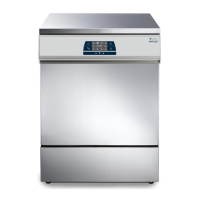
Select the SOLENOID VALVES menu and press ENTER conrm.
The screen shows the states of the ve solenoid valves of the manifold;
state labels are as follows:
solenoid valve open
solenoid valve closed
During a COMPONENT TEST, with the door open, all solenoid valves (EV)
are powered off.
The FAN indicator shows the On/Off state of heat exchanger fans.
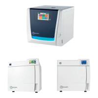
SQ7
From the SOLENOID VALVES menu, you can turn the individual solenoid
valves and radiator fans on and off.
Solenoid valves and fans can be operated using the suitable touch control.
Several elements can be turned on at the same time to check specic
sections of the hydraulic circuit.
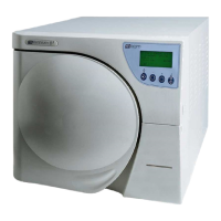
SQ8
Select the OTHER COMPONENTS menu and press ENTER to conrm.
The screen shows the following components:
- BH – chamber tube bundle heating element
- SG – generator heating element
- VP – vacuum pump
- WP – water injection pump/EV6
The following values are also displayed:
- PT1 – chamber temperature
- PT2 – steam generator temperature
- PT3 – chamber tube bundle heating element temperature
- P – chamber pressure
SQ9
From the OTHER COMPONENTS menu, you can establish the state of
individual components, which can be turned on and off using the touch
control.
BH activation is indicated by parameter PT3 chamber tube bundle heating
element temperature increasing.
SG activation is indicated by parameter PT2 steam generator temperature
increasing.
A safety timeout is provided for the BH and SG functions, so that the
relevant component is turned off after 120”.
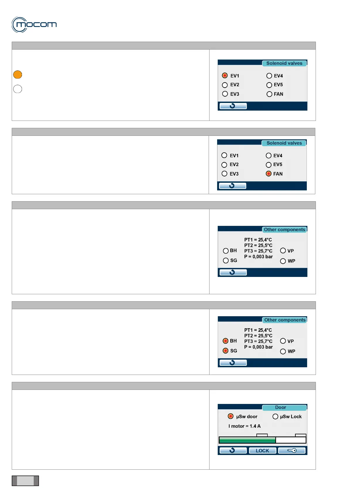
SQ10
From the DOOR menu, you can establish the states of door and door
microswitches and manually activate door lock, release and complete
opening.
The following indicators are displayed:
- μSw Door – manual door closing microswitch
- μSw Lock – door lock enable microswitch
- I motor – motor current draw
During the door closing and locking phases, the variations in parameter I
motor are shown by the digital bar at the bottom of the DOOR screen.
 Loading...