EasyManua.ls Logo

Mocom millennium B Service Manual

Mocom millennium B
285 pages
To Next Page IconTo Next Page
Page #1 background imageLoading...
Page #1 background image
Rev. 1

Table of Contents

Question and Answer IconNeed help?

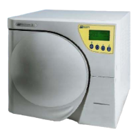
Do you have a question about the Mocom millennium B and is the answer not in the manual?

Mocom millennium B Specifications

General IconGeneral
BrandMocom
Modelmillennium B
CategoryLaboratory Equipment
LanguageEnglish

Summary

1. UTILIZATION

GENERAL

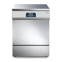
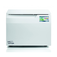
General information about the sterilizer, directives, notes, warnings, and customer service.

INSTALLATION

Covers general installation, packing, handling, precautions, electrical connections, and Millflash connection.

CONFIGURATION

Information on personalizing the device and entering the Setup Mode.

ACTIVATING CONFIGURATION OPTIONS – BASIC MENU

Basic configuration options like language, date, time, and password settings.

ACTIVATING CONFIGURATION OPTIONS – ADVANCED MENU

Advanced settings for sterilization programs, stand-by modes, printer, and filling/draining options.

1. UTILIZATION

PREPARING THE MATERIAL TO BE STERILIZED

General guidelines and precautions for preparing materials before sterilization.

STORING STERILIZED MATERIAL

Guidelines for adequately treating and storing sterilized material.

FIRST START-UP

Steps for initial setup and operation.

MAINTENANCE

General maintenance guidelines and the ordinary maintenance program.

GENERAL

APPLICABLE EUROPEAN DIRECTIVES

Information on the European directives the product complies with.

SYMBOLS USED THROUGH THE MANUAL

Explanation of symbols used in the manual to indicate warnings and dangers.

GENERAL WARNINGS

INTENDED USE

Specifies the intended use of the device and restrictions on personnel.

PRODUCT OVERVIEW

FRONT VIEW

REAR VIEW

CONTROL PANEL LCD DISPLAY

TECHNICAL CHARACTERISTICS

SAFETY DEVICES

CHARACTERISTICS OF THE FILLING WATER

INSTALLATION

GENERAL

Emphasizes the importance of correct installation for operation, longevity, and safety.

PACKING CONTENT

HANDLING THE PRODUCT

GENERAL INSTALLATION PRECAUTIONS

COMPARTMENT DIMENSIONS FOR BUILT-IN INSTALLATIONS

Minimum dimensions required for built-in installations to ensure adequate ventilation and cooling.

ELECTRICAL CONNECTIONS

CONFIGURATION

Starting and entering the Setup Mode

Steps to start the SETUP program and enter the Setup Mode.

Menu items

BASIC menu

Details items within the Basic menu: Language, Date, Time, Password, Exit.

ADVANCED menu

Details items within the Advanced menu: Programmes, Stand-by, Print, Filling, Drain, Exit.

SPECIAL menu

Details items within the Special menu: Ambient Pressure, LCD Contrast, Exit.

SERVICE menu

Lists options accessible only by Service department: Component Test, Test Cycles, etc.

ACTIVATING CONFIGURATION OPTIONS – BASIC MENU

Setting the language

How to select and set the display language for the menus.

Setting the Date

Procedure for setting the current date.

ACTIVATING CONFIGURATION OPTIONS – BASIC MENU

Setting the Time

Procedure for setting the current time.

Setting the Password

Options for setting passwords to restrict access to the device.

ACTIVATING CONFIGURATION OPTIONS – ADVANCED MENU

Setting the sterilization programs

How to associate standard or custom sterilization programs to preset positions.

ACTIVATING CONFIGURATION OPTIONS – ADVANCED MENU

Setting the STAND-BY modes

How to select heating level and deactivation time for STAND-BY mode.

ACTIVATING CONFIGURATION OPTIONS – ADVANCED MENU

Setting the Printer mode

Parameters for setting up the printer for recording sterilization program data.

ACTIVATING CONFIGURATION OPTIONS – ADVANCED MENU

Setting the tank Filling mode

Options for filling the internal tank manually or automatically.

ACTIVATING CONFIGURATION OPTIONS – ADVANCED MENU

Setting the Water Draining mode

How to collect used water into the internal or an external tank.

ACTIVATING CONFIGURATION OPTIONS – SPECIAL MENU

Acquisition of the ambient pressure

Procedure for acquiring ambient pressure for auxiliary systems.

ACTIVATING CONFIGURATION OPTIONS – SPECIAL MENU

Adjusting the contrast of the liquid crystal display

How to adjust LCD contrast for better readability.

ACTIVATING CONFIGURATION OPTIONS – SERVICE MENU

SERVICE

DEVICE TEST

How to check any device of the sterilizer.

TEST CYCLES

Setting different test procedures according to technician needs.

H2O CIRCUIT

Checking the hydraulic circuit and water filling operation.

PT1 CORRECTION

Setting the Ohm value of the internal probe after repair.

Device Test

AUTOMATIC

Automatic test sequence for devices.

Test cycles

SPECIAL CYCLE

Performing a full test of the sterilizer.

CONTINUOUS CYCLE

Enabling a test based on continuous repetition of a selected cycle.

NO VACUUM CYCLE

Enabling a test with pressure pulses and without vacuum phases.

H2O CIRCUIT

Counter reset

Factory Data

Technical report

PT1 correction

DATA REVIEW

EXIT THE SETUP MODE

DEFAULT SETTING

PREPARING THE MATERIAL TO BE STERILIZED

General

Emphasizes proper treatment and arrangement of material.

Treating the material before sterilization

Precautions for handling contaminated materials and ensuring items are clean.

Arranging the load

General notes for positioning on trays

Guidelines for positioning instruments and materials on trays for optimal sterilization.

Notes for rubber and plastic tubing

Specific notes for arranging rubber and plastic tubing on trays.

Notes for packets and packages

Notes for wrapped material

Instructions for wrapping instruments individually or in groups.

STORING STERILIZED MATERIAL

General

Importance of proper storage to maintain sterility and prevent recontamination.

Handling

Precautions for handling and carrying sterile material.

Storage

Techniques for storing sterile material to slow recontamination.

FIRST START-UP

Turning on

Steps to turn on the sterilizer.

Initial automatic test

Describes the initial automatic test and display messages.

Stand-by mode

Filling distilled water

Manual filling

Step-by-step instructions for manually filling the distilled water tank.

Automatic filling

How automatic filling works and its setup.

MAX level in the internal/ external drain tank

Emptying the internal tank

Procedure for emptying the internal drain tank.

Emptying the external tank

Instructions for emptying the external drain tank.

MAINTENANCE

GENERAL

Notes on periodic examinations and sterilizer validation.

ORDINARY MAINTENANCE PROGRAM

Summary of routine maintenance tasks.

General notes

Maintenance description

Clean the gasket and porthole

How to remove lime traces from the gasket and porthole.

Clean external surfaces

Cleaning the external parts of the sterilizer.

Maintenance description

Clean sterilization chamber and accessories

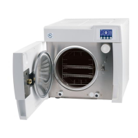
Cleaning the sterilization chamber, support, and trays.

Disinfect external surfaces

Methods for disinfecting external surfaces.

Clean internal distilled water tank

Procedure for cleaning the internal distilled water tank.

Clean external distilled water tank

Procedure for cleaning the external distilled water tank.

Safety valve maintenance

Clean (or replace) the water drain filter

Replace bacteriological filter

Replace the printer paper

Periodic sterilizer validation

2. OPERATION

THE PROGRAMS AVAILABLE

Overview of available sterilization programs.

SELECTING THE STERILIZATION PROGRAM

How to select the most suitable program for different materials.

RUNNING THE STERILIZATION PROGRAM

General information on sterilization cycles and parameter monitoring.

SEQUENCE OF THE PROCESS

Detailed phase-by-phase description of a sterilization cycle.

TEST PROGRAMS

Overview of Helix/BD Test and Vacuum Test programs for safety checks.

CYCLE DIAGRAMS

Visual representation of various sterilization cycle phases.

THE PROGRAMS AVAILABLE

GENERAL

Information on materials suitable for steam sterilization and program selection.

PROGRAM SUMMARY TABLE

SELECTING THE STERILIZATION PROGRAM

RUNNING THE STERILIZATION PROGRAM

General

Description of sterilization cycle phases and parameter monitoring.

Starting the program

Door locking

SEQUENCE OF THE PROCESS

Standby status

Display information and statuses during standby.

SEQUENCE OF THE PROCESS

Warmup

The first phase of the cycle, bringing the chamber to temperature.

SEQUENCE OF THE PROCESS

1st vacuum pulse – PV1

The first vacuum phase, lowering chamber pressure.

SEQUENCE OF THE PROCESS

1st pressure pulse – PP1

Steam injection and pressure rise phase.

SEQUENCE OF THE PROCESS

2nd vacuum pulse- PV2

Discharge of steam and air, and the second vacuum phase.

SEQUENCE OF THE PROCESS

2nd pressure pulse – PP2

Steam injection and pressure rise phase.

SEQUENCE OF THE PROCESS

3rd vacuum pulse – PV3

Discharge and the final vacuum phase.

SEQUENCE OF THE PROCESS

3rd pressure pulse – PP3

Final steam injection and pressure rise.

SEQUENCE OF THE PROCESS

Thermodynamic equilibration

Stabilizing temperature and pressure in the chamber.

SEQUENCE OF THE PROCESS

Process

The actual sterilization phase (holding time) where parameters are maintained constant.

SEQUENCE OF THE PROCESS

Steam discharge

Releasing steam from the sterilization chamber.

SEQUENCE OF THE PROCESS

Drying

Forced removal of steam using vacuum pump to evaporate and eliminate moisture.

SEQUENCE OF THE PROCESS

Ventilation

Injecting sterile air to eliminate condensate and cool the load.

SEQUENCE OF THE PROCESS

Levelling

Bringing the chamber back to atmospheric pressure to allow door opening.

SEQUENCE OF THE PROCESS

Completion of the cycle

Door lock release, cycle complete indication, and retrieving sterilized material.

MANUAL CYCLE INTERRUPTION

RESULT OF THE CYCLE

PRINT OF THE CYCLE REPORT

TEST PROGRAMS

GENERAL

Purpose and types of test programs.

HELIX/BD TEST

Details of the Helix/BD Test program, including device and execution.

VACUUM TEST

CYCLE DIAGRAMS

3. TROUBLESHOOTING AND REPAIR

TROUBLESHOOTING

General information on alarms, codes, and intervention procedures.

GENERAL

Categories of alarm codes (E, A, H) and their format.

ALARM INTERVENTION

Procedures to follow in case of an alarm.

REPAIR PROCEDURES

GROUP 1 ELECTRONIC DEVICES AND ASSEMBLIES

Repair procedures for electronic devices and assemblies.

GROUP 2 ELECTROVALVES

Repair procedures for electrovalves.

GROUP 3 PUMPS

Repair procedures for pumps.

GROUP 4 PLUMBING CIRCUIT

Repair procedures for the plumbing circuit.

GROUP 5 WIRINGS

Repair procedures for wirings.

GROUP 6 DOOR LOCKING MECHANISM

Repair procedures for the door locking mechanism.

TROUBLESHOOTING

GENERAL

How alarms are generated and categorized.

ALARM INTERVENTION

Actions to take during an alarm, including cycle interruption and reset.

Alarm during a cycle

Alarm during a cycle

Alarm outside the cycle

Display messages when an alarm occurs outside a program.

RESETTING THE SYSTEM

ERROR LIST - “E” CODES

ALARM LIST - “A” CODES

ALARM LIST - “A” CODES

HAZARD ALARM LIST - “H” CODES

E 000

E 010

E 020

E 021

E 030

E 031

E 041

E 900

E 901

E 902

E 999

A 022

A 023

A 024

A 032

A 040

A 101

A 102

A 103

A 104

A 111

A 112

A 113

A 114

A 200

A 250

A 251

A 252

A 253

A 254

A 255

A 256

A 257

A 258

A 259

A 260

H 150

H 160

H 400

H 401

H 402

H 403

H 404

H 405

H 406

H 410

H 990

H 991

H 992

H 993

REPAIR PROCEDURES

GROUP 1 ELECTRONIC DEVICES AND ASSEMBLIES

Repair procedures for electronic devices and assemblies.

GROUP 2 ELECTROVALVES

Repair procedures for electrovalves.

GROUP 3 PUMPS

Repair procedures for pumps.

GROUP 4 PLUMBING CIRCUIT

Repair procedures for the plumbing circuit.

GROUP 5 WIRINGS

Repair procedures for wirings.

GROUP 6 DOOR LOCKING MECHANISM

Repair procedures for the door locking mechanism.

GROUP 1 ELECTRONIC COMPONENTS AND ASSEMBLIES

ELECTRONIC BOARD ASSEMBLY (GAM VERSION)

ELECTRONIC BOARD ASSEMBLY (TROLL VERSION)

LCD BOARD

KEYBOARD

PRESSURE TRANSDUCER

PRESSURE SWITCH

FIRMWARE EPROM

TRANSFORMER ASSEMBLY

PT1 PROBE

PT2 PROBE

PT3 PROBE

PT4 PROBE

STEAM GENERATOR THERMOSTAT

CHAMBER HEATER THERMOSTAT

MAINS FUSE HOLDERS

MAINS FUSES

ON-BOARD PCB FUSES

MAIN SWITCH

BAND CHAMBER HEATER

CARTRIDGE RESISTORS

CUSTOM PRINTER UNIT

FENIX PRINTER UNIT

EV1 VALVE / COIL / SHAFT

EV2 VALVE / COIL / SHAFT

EV2 – EV3 ASSEMBLY

Procedure for replacing the EV2-EV3 assembly.

EV3 VALVE / COIL / SHAFT

EV2 – EV3 ASSEMBLY

Procedure for replacing the EV2-EV3 assembly.

EV4 VALVE / COIL / SHAFT

EV5 VALVE / COIL / SHAFT

GROUP 3 PUMPS

STEAM GENERATOR WATER PUMP ASSEMBLY

AUTOMATIC WATER FILLING PUMP ASSEMBLY

VACUUM DOUBLE PUMP ASSEMBLY

GROUP 4 PLUMBING CIRCUIT

WATER TANK ASSEMBLY

MIN AND MAX WATER LEVEL PROBES (DISTILLED WATER TANK)

MAX WATER LEVEL PROBE (USED WATER TANK)

Procedure for replacing the MAX water level probe.

HEAT EXCHANGER

ELECTRIC FAN

HEAT EXCHANGER ASSEMBLY

STEAM GENERATOR ASSEMBLY

BACTERIOLOGICAL FILTER

SAECO FILTER ON THE WATER PUMPS

LP1 FILTER

PIPES AND FITTINGS

SAFETY VALVE ASSEMBLY

GROUP 5 WIRING

WATER PUMPS

VACUUM PUMP

DOOR MICROSWITCH

ELECTROVALVES

PRINTER SIGNAL

PRINTER POWER SUPPLY

MOTOR AND PRESSURE SWITCH

STEAM GENERATOR GROUND WIRE

CHAMBER GROUND WIRE

MAINS SWITCH

POWER SUPPLY

THERMOSTAT

GROUP 6 DOOR-LOCKING MECHANISM

DOOR GASKET

PARABOLA

DOOR FORK AND PIN

DOOR POSITIONER

DOOR-CLOSED SWITCH

GEAR-MOTOR

GROUP 7 COVERS

LEFT-SIDE COVER

TOP COVER

SINGLE COVER

DOOR COVER

FRONT FRAME ASSEMBLY

SERVICE DOOR

ATTACHMENTS

Attachment A - Adjust Door Positioner

Procedure for adjusting the door positioner.

Attachment B - Adjust Parabola

Procedure for adjusting the parabola.

Attachment C - Replace Printer Paper Roll

Procedure for replacing the printer paper roll (Fenix type).

Attachment D - Install Printer Kit

Procedure for installing the printer kit.

Attachment G - Start-Up Steam Generator

Procedure for starting up the steam generator under specific conditions.

Attachment H - Release Door Locking Mechanism via Software

Software method to release the door locking mechanism.

Attachment I - Release Door Locking Mechanism manually

Manual procedure to release the door locking mechanism.

Attachment J - Recover Default Data

Procedure for recovering default data and subsequent calibration.

Attachment K - Update Software

Procedure for updating the sterilizer software on GAM boards.

Attachment L - Release Alarm A022 - Door Locked

Procedure to release the A022 alarm (Door Locked).

Attachment M - Check Calibration

Procedure for checking calibration of sensors and parameters.

Attachment N - Calibration

Detailed calibration procedures for GAM and TROLL electronic boards.

Attachment O - Test the Unit through Continuous Cycles

Procedure for testing the sterilizer using continuous cycles.

ATTACHMENT A - ADJUST DOOR POSITIONER

ATTACHMENT B - ADJUST PARABOLA

ATTACHMENT C - REPLACE PRINTER PAPER ROLL

Custom type

ATTACHMENT D - INSTALL PRINTER KIT

ATTACHMENT E - RESET PRINT QUEUE

ATTACHMENT F - CHECK PRINTER PAPER FEEDING

ATTACHMENT G - START-UP STEAM GENERATOR

ATTACHMENT H - RELEASE DOOR LOCKING MECHANISM VIA SOFTWARE

ATTACHMENT I - RELEASE DOOR LOCKING MECHANISM MANUALLY

ATTACHMENT J - RECOVER DEFAULT DATA

ATTACHMENT K - UPDATE SOFTWARE

TROLL electronic boards (use of Millprog device)

ATTACHMENT L - RELEASE ALARM A022 - DOOR LOCKED

ATTACHMENT M - CHECK CALIBRATION

ATTACHMENT N - CALIBRATION

ATTACHMENT O - TEST THE UNIT THROUGH CONTINUOUS CYCLES

4. DIAGRAMS, ESPLODED VIEWS, SPARE PARTS

DIAGRAMS

Electrical and hydraulic diagrams for the sterilizer.

EXPLODED VIEWS

Visual breakdown of sterilizer components.

SPARE PARTS

List of spare parts with part numbers and references.

DIAGRAMS

CIRCUIT DIAGRAM (GAM version)

Electrical circuit diagram for the GAM version of the sterilizer.

CIRCUIT DIAGRAM (TROLL version)

HYDRAULIC DIAGRAM

EXPLODED VIEWS

TABLE 1

Exploded view of the sterilizer's external components and chassis.

EXPLODED VIEWS

TABLE 2

Exploded view of the sterilization chamber and related parts.

EXPLODED VIEWS

TABLE 3

Exploded view of the sterilizer's internal electronic and power components.

EXPLODED VIEWS

TABLE 4

Exploded view of various components including fans, heating elements, and motors.

EXPLODED VIEWS

TABLE 5

Exploded view of various components including fans, valves, and heat exchangers.

EXPLODED VIEWS

TABLE 6

Exploded views of electrovalves and their assemblies.

TABLE 7

SPARE PARTS

Related product manuals