Rev. 1
Attach.
15
ATTACHMENT M -
CHECK CALIBRATION
Before servicing, switch off the equipment and unplug the power
supply cable from the mains socket
1. Remove the covers (see card Gr7-1 );
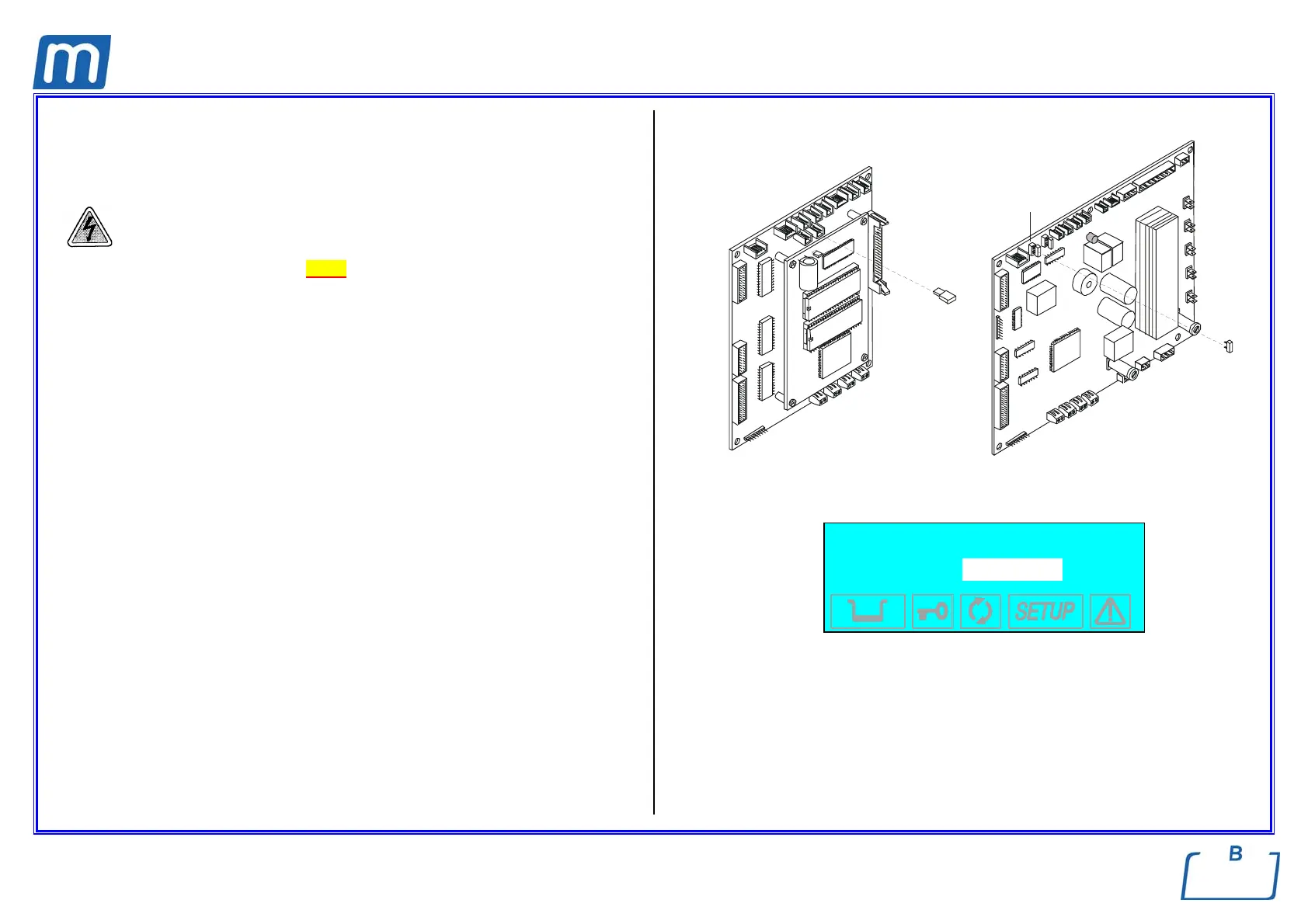
2. Unplug jumper X21 of the CPU board;
3. Remove the wirings of any PT probes;
4. Plug-in the sample connector provided with the pin for checking value 000,0;
5. Press the Start key and switch-on the unit; LCD will show the message
“SETUP” and then the PT1 value (see figure);
6. Check that PT1 value matches the calibration one, i.e. 000,0;
7. Press the Start key and repeat the check for PT2, PT3 and PT4 on the
relating connector;
8. Should any value to be different from the calibration one, use key + and – to
increase or decrease the value;
9. At the end of the last check, remove the sample connector, plug-in it again in
reverse direction in order to check PTn value at 130.4° reference;
10. Repeat the check for any PTn as above, and adjust the value in case of
mismatch from 000,0;
11. Ended the PTn checks, push again key Start to continue with the next check,
i.e. pressure transducer at 0,00 , 2,10 and -.90 bar;
12. Press the Start key, the display will show “SETUP COMPLETE”;
13. Press again the Start key to exit the calibration function and launch the self-
test;
14. At the end of the self-test, switch-off the unit and restore the jumper X21;
15. Switch-on the unit and perform a sterilization cycle;
X21
GAM TROLL
X21
Example of LCD display
PT1 000,0
015,0 7.395
Sensor
Value to be edited in
order to match the
reference one
Reference value
Ohm value