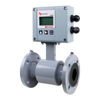
Chemical Injection Applications
For water line applications with a chemical injection point, install the meter
upstream of the injection point. This eliminates any meter performance issues.
Figure 15: Chemical injection point downstream of meter
If a meter must be installed downstream of a chemical injection connection,
the distance between the flange and the injection point should be between
50…100 feet (15…30 meters). The distance must be long enough to
allow the water or chemical solution to reach the meter in a complete,
homogeneousmixture.
Figure 16: Chemical injection point upstream of meter
If the injection point is too close, the meter senses the two different conductivities for each liquid. This will likely result in
inaccurate measurements. The injection method—spaced bursts, continuous stream of drips or liquid or gas—can also affect
downstream readings by the meter.
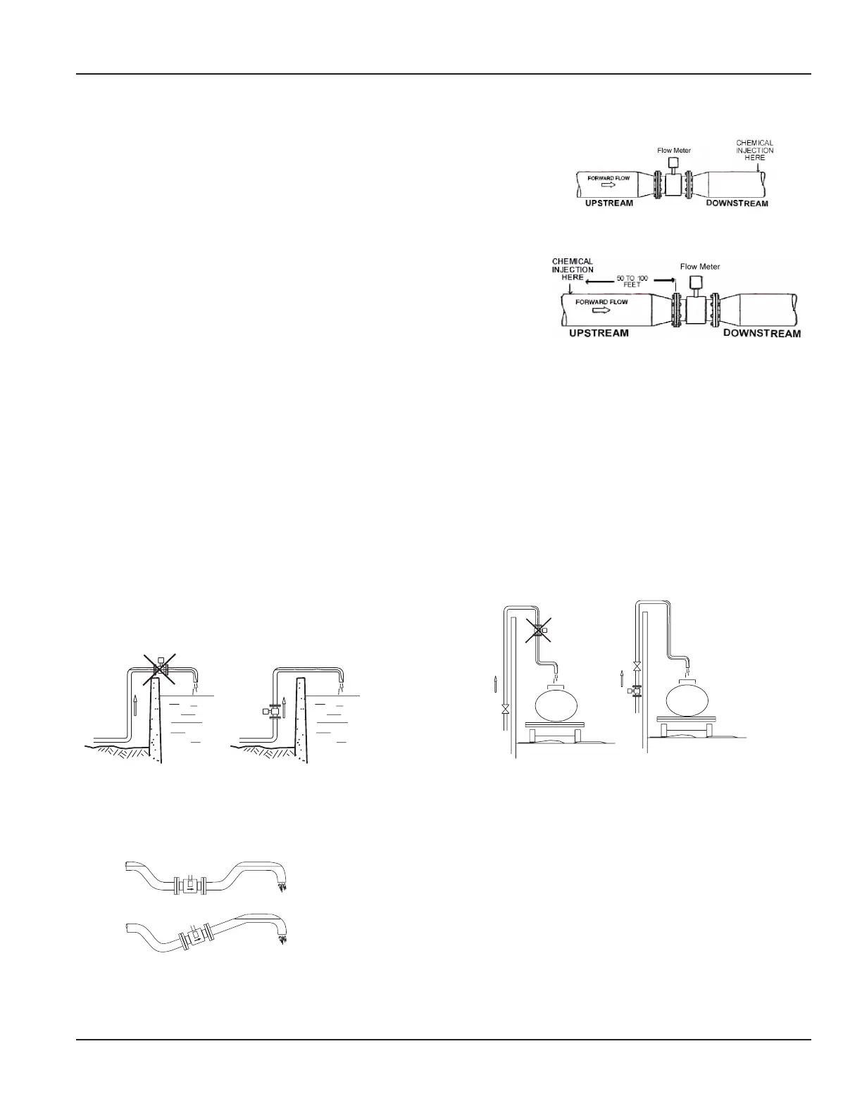
Partially Filled Pipe Situations
In some locations, the process pipe may be momentarily only partially filled. Examples include: lack of back pressure,
insufficient line pressure and gravity flow applications.
To eliminate these situations:
• Do not install the meter at the highest point of the pipeline.
• Do not install the meter in a vertical, downward flow section of pipe.
• Always position the ON/OFF valves on the downstream side of the meter.
FLOW
FLOW
FLOW
WRONG
FLOW
RIGHT
Figure 17: Meter placement
Do not install in a vertical, downward position. Position "On/Off" valves on downstream side.
Figure 18: Position valves on downstream side
To minimize the possibility of partially full pipe flows in horizontal, gravity or low pressure applications, create a pipe
arrangement that allows the detector to remain full of liquid at all times.
Figure 19: Pipe positioned to keep water in detector
Meter Location, Orientation and Applications
Page 13 March 2020 MAG-UM-00379-EN-07