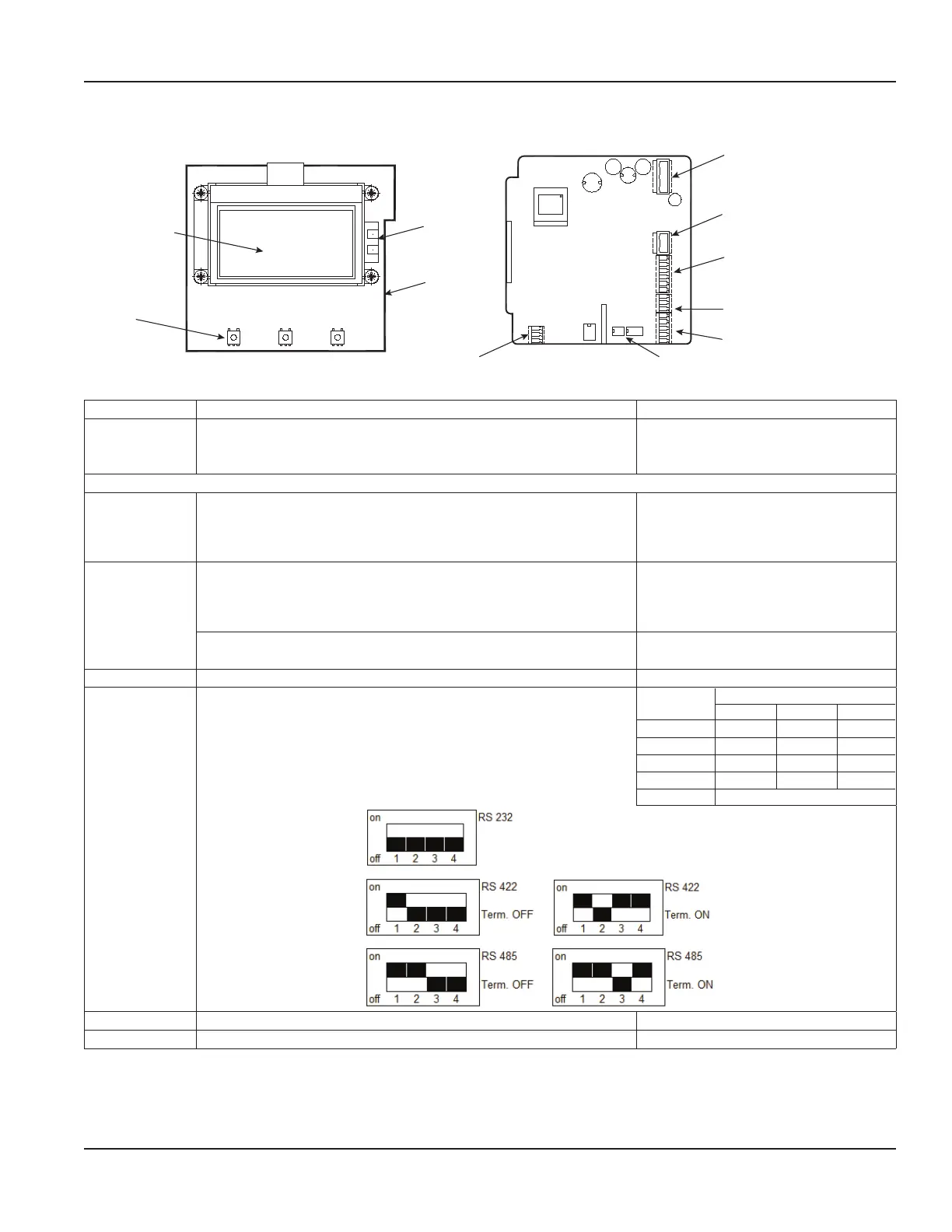
Conguring Input/Output (I/O)
S1
S2
1
2
3
4
5
6
7
8
9
A
B
Z
Y
G
Solid-state relays (Terminals S1, S2)
Digital input/output
(Terminals 1, 2, 3, 4, 5, 6)
Analog output (Terminals 7, 8, 9)
RS interface (Terminals A, B, Z, Y, G)
RS interface switchCoil detector
USB port
Ethernet
Display
Figure 28: Configuring I/O
Input/Output Description Terminal
Analog Output 0…20 mA
4…20 mA
0…10 mA
RL < 800 Ohm 7 (+)
8 (–)
9 (GND)
Digital Output
1 Open collector max. 10 kHz
• Passive max. 32V DC, <100 Hz 100 mA, >100 Hz 20 mA
• Active 24V DC, 20 mA (can be powered by analog output if
not used)
3 (–)
4 (+)
2 Open collector max. 10 kHz
• Passive max. 32V DC, <100 Hz 100 mA, >100 Hz 20 mA
• Active 24V DC, 20 mA (can be powered by analog output if
not used)
1 (–)
2 (+)
Solid-state relays max. 230V AC, 500 mA, max 1 Hz
(Function is linked with Output 2)
S1 and S2
Digital Input 5…30V DC 5 (–) and 6 (+)
RS-Interfaces RS-232, RS-485 and RS-422 with Modbus® RTU.
Mode can be configured by DIP switches when termination is ON
or OFF.
Connector
Label
RS Interfaces
422 232 485
A A RxD —
B B — —
Z Z TxD B
Y Y — A
G G (GND)
USB USB Device CDC (Host Mass Storage) Micro USB
Ethernet Ethernet interface connection RJ45 socket
Power Connections
Page 21 March 2020 MAG-UM-00379-EN-07
 Loading...