Do you have a question about the ModMAG M1000 and is the answer not in the manual?
Read manual thoroughly. Only qualified personnel should install/repair. Contact distributor for faults.
Do not place on unstable surfaces. Route cabling away from hazards. Isolate from mains before removing covers.
Use suitable power source, high current rating cables. Ensure all units are earthed to eliminate shock risk.
Device has IP 67 protection. Protect against dripping water, oils, and other liquids.
Adjust only specified controls. Improper adjustment may cause damage or data loss.
Ensure cavities are free of dangerous substances after operation before removing the device.
The M1000 meter is compliant with RoHS regulations.
Based on Faraday's induction principle, measuring voltage induced by fluid in a magnetic field.
Check device nameplate for correct supply voltage and order details upon delivery.
Use soft straps, lifting lugs for large units. Avoid forks on housing or liner. Do not lift by amplifier or cables.
Integral/meter mount or junction box/remote mount configurations available.
Observe maximum temperature limits for amplifier and detector. Protect amplifier from direct sunlight.
Avoid suction side, highest points, downcomer pipes. Secure against vibration. Prevent electrical interference.
Protect from elements. Ambient rating -4 to 140°F. Consider indoor mounting if within 150 ft.
Minimum 3x DN upstream and 2x DN downstream straight pipe required for accuracy.
Ideal for full pipes, liquid flowing upward. Prevents solids build-up on electrodes.
Utilizes Empty Pipe Detection. Mount with electrode axis horizontal for solids prevention.
3x DN upstream and 2x DN downstream required for optimal meter accuracy.
Custom reducers require ~8 degree slope angle to minimize flow disturbances.
Install meter upstream of injection point. If downstream, ensure 50-100 ft for mixture homogeneity.
Avoid highest pipe points/downward flow. Position valves downstream. Ensure pipe remains full.
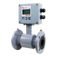
Amplifier mounted directly on detector for compact, self-contained installation.
Amplifier located away from detector for high temp (>212°F) or vibration environments.
For vault installation, order submersible amplifier. Do not install amplifier inside vault.
Ensure seals are intact, screws tight, and cable inlets correctly used.
Use fluid-compatible gaskets between detector liner and flange for hydraulic seal.
Connect amplifier input ground to liquid media and earth ground using grounding bolts.
Connect meter body to liquid media. Install grounding straps between flanges and grounding bolts.
Install with potential-free contacts. No direct electrical connection to pipeline. Use isolating transformer.
Use grounding rings between flanges for non-conductive pipes. Connect straps to rings and earth ground.
Disconnect power before work. Avoid bundling signal/power lines. Use twisted shielded wire for outputs.
Step-by-step guide on how to open the amplifier cover without complete removal.
Connect main power only after all other wiring is complete. Observe type plate and use disconnect means.
Connect signal cable to measuring amplifier or junction box with unit switched off.
Use specified cables. Max length 164 ft (50m). Check PVC cable, shield, and loop resistance.
Chart illustrating maximum signal cable length based on fluid temperature.
Configure analog output ranges (0-20mA, 4-20mA, 0-10mA) and digital I/O functions.
Set RS-232, RS-485, RS-422 modes using DIP switches for communication.
Use shielded cables for normal I/Os, connect shield to ground. Specify LiYCY cable size.
Use separate inlets for solid state relay and other I/Os. Ensure phase consistency in multiphase nets.
Overview of display elements: header, submenu, scrollbar, and status icons for meter conditions.
Guide to using the three function buttons for menu navigation, selection, and parameter changes.
Details calibration, scale factor, power line frequency, excitation frequency, and empty pipe settings.
Covers flow units, totalizer units, full scale, low flow cutoff, and flow direction settings.
Includes analog output, digital input, digital outputs (pulse, frequency, preset), and simulation.
Configure Modbus, M-Bus, HART, Ethernet, and ADE interfaces for data communication.
Manage language, date, time, EEPROM, display settings, serial number, and version.
Covers diameter, detector factor, detector zero, amplifier factor, scale factor, and coil current.
Includes power line frequency, excitation frequency, and empty pipe detection parameters.
Choose units for flow measurement and totalizers from available options.
Set maximum full scale flow and low flow cutoff threshold for accurate measurement.
Configure uni-directional or bi-directional flow measurement and totalization modes.
Reduces signal noise by adjusting filter level from 7 to 13 or switching it off.
Smooths short-term fluctuations; adjustable 1-200 periods, delay depends on excitation frequency.
Set current output range (0-20mA, 4-20mA, 0-10mA) and define alarm mode behavior.
Used for totalizer reset or flow measurement interrupt. Accepts external 5-30V DC potential.
Configure pulse width, pulses per unit, frequency, set point, and preset amount.
Define functions for Out 1 and Out 2, including pulse types and active/passive output modes.
Relay linked to Output 2, supports various functions like error, direction, and alarm indication.
Set output switch (NO/NC) and enable flow simulation mode for testing.
Configure Modbus RTU, RS-232, RS-485, RS-422 settings, address, baud rate, and parity.
Set up Ethernet IP, Gateway, MAC, and ADE Control/Protocol for network communication.
Adjust power up count, settling time, language, date, time, EEPROM, display rotation, and contrast.
Configure logging period, check memory capacity, and view device serial number and software version.
Define 6-digit PINs for Administrative, Service, and User access to restrict menu access.
Instructions for activating password protection, logging in, and logging out of the system.
Guidelines for cleaning flow tube and electrodes, referencing MSDS for safe practices.
Perform general cleaning with a damp cloth after disconnecting power and isolating the unit.
Lists error descriptions, possible causes, and recommended actions for detected malfunctions.
Addresses issues like meter not functioning, zero display with flow, or inaccurate measurements.
Disconnect and have faulty units repaired by qualified personnel if damaged or malfunctioning.
Explains the meaning of LEDs on the main and display boards for device status monitoring.
Step-by-step guide for replacing meter electronics, including power disconnection and configuration.
Details terminal connections between the M1000 and the AquaCUE/BEACON encoder interface.
Configures M1000 communication parameters (ADE, Protocol, Resolution) for the external interface.
Covers size, connections, pressure, conductivity, liners, electrodes, body, and grounding rings.
Provides dimensions for Type II flange remote and mounted versions.
Specifies dimensions and pressure for food-grade Tri-Clamp connections.
Specifies dimensions and pressure for food-grade DIN 11851 connections.
Details dimensions for BS4825 and ISO2852 standard connections.
Details Tri-Clamp, DIN 11851, ISO2852, BS4825 connections and materials.
Provides overall length and connection dimensions for remote mount versions.
Provides dimensions for food-grade Tri-Clamp mounted detector versions.
Provides dimensions for food-grade DIN 11851 mounted detector versions.
Covers size, sandwich connections, pressure, conductivity, liners, electrodes, and body materials.
Provides dimensions for Type III wafer remote and mounted versions.
Details power, outputs, inputs, frequency, range, accuracy, reproducibility, and low flow cutoff.
Covers display, housing, mounting, protection class, cable, altitude, temperature, humidity, and approvals.
Specifies measuring range, pulse output, analog output, and reproducibility error limits.
Defines temperature, conductivity, warm-up, and mounting conditions affecting measurement accuracy.
Provides US and Metric flow ranges for various meter sizes (DN) for selection.
Lists part numbers for amplifier assemblies and circuit boards (110V AC, 24V DC).
Lists part numbers for covers, mounting kits, cable glands, and remote mounting kits with cable.
Includes part numbers for data logging kits, firmware upgrades, and communication interface kits.
| Brand | ModMAG |
|---|---|
| Model | M1000 |
| Category | Measuring Instruments |
| Language | English |