SR5 Technical Manual TSP010.doc Issue 3.0 - October 2001
CONFIDENTIAL
Not to be disclosed without prior written permission from Money Controls
Page 26 of 50
16) Diagnostics
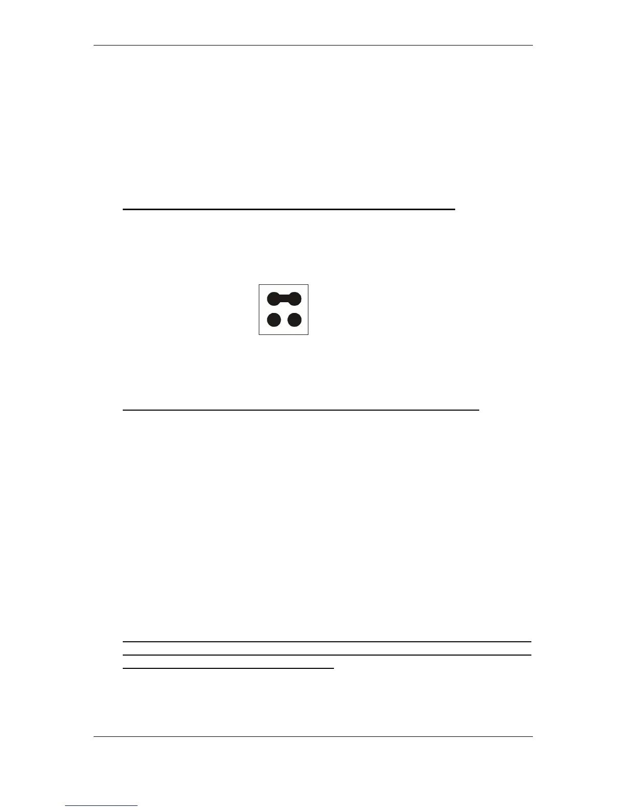
The operation of 3 diagnostics modes are available via connector 7
(
Figure 2).
The connector has two inputs. If either or both inputs are Low then diagnostics
mode can be activated. When both inputs are High – not connected - (inactive)
the SR5 is in normal run mode.
To enter diagnostics mode, set the jumpers to perform the required test, set the
rotary switch to position 0, then press the program button 11
(
Figure 2)
until the
LED flashes Yellow.
NB: If the LED stays Green then Diagnostics is not available.
Two jumpers may be used to select the following modes:
♦ Inhibit/Accept line and Inductive Noise Test
This mode is used for checking inhibit and accept lines in a loop-back test.
Only the status of inhibit lines 1 to 6 are used.
The inhibit line must be Low to activate the corresponding accept line.
Inhibit 1
⇒
Accept 1
Inhibit 2
⇒
Accept 2
Inhibit 3
⇒
Accept 3
Inhibit 4
⇒
Accept 4
Inhibit 5
⇒
Accept 5
Inhibit 6
⇒
Accept 6
Inhibit 7 and 8
⇒
Not used
The SR5 will also ‘clap’ the accept gate a number of times, depending on the
level of noise present on the sensors. The more ‘claps’, the more noise.
0 claps No detectable noise.
1 to 5 claps Small amount of noise – acceptable.
>5 claps Unacceptable amount of noise.
NB: This only happens when the diagnostics mode is first entered. In order to
repeat, press the program button, the LED will turn green. Press the program
button again until the LED flashes yellow.
0V
0V
Jumper
 Loading...