SR5 Technical Manual TSP010.doc Issue 3.0 - October 2001
CONFIDENTIAL
Not to be disclosed without prior written permission from Money Controls
Page 8 of 50
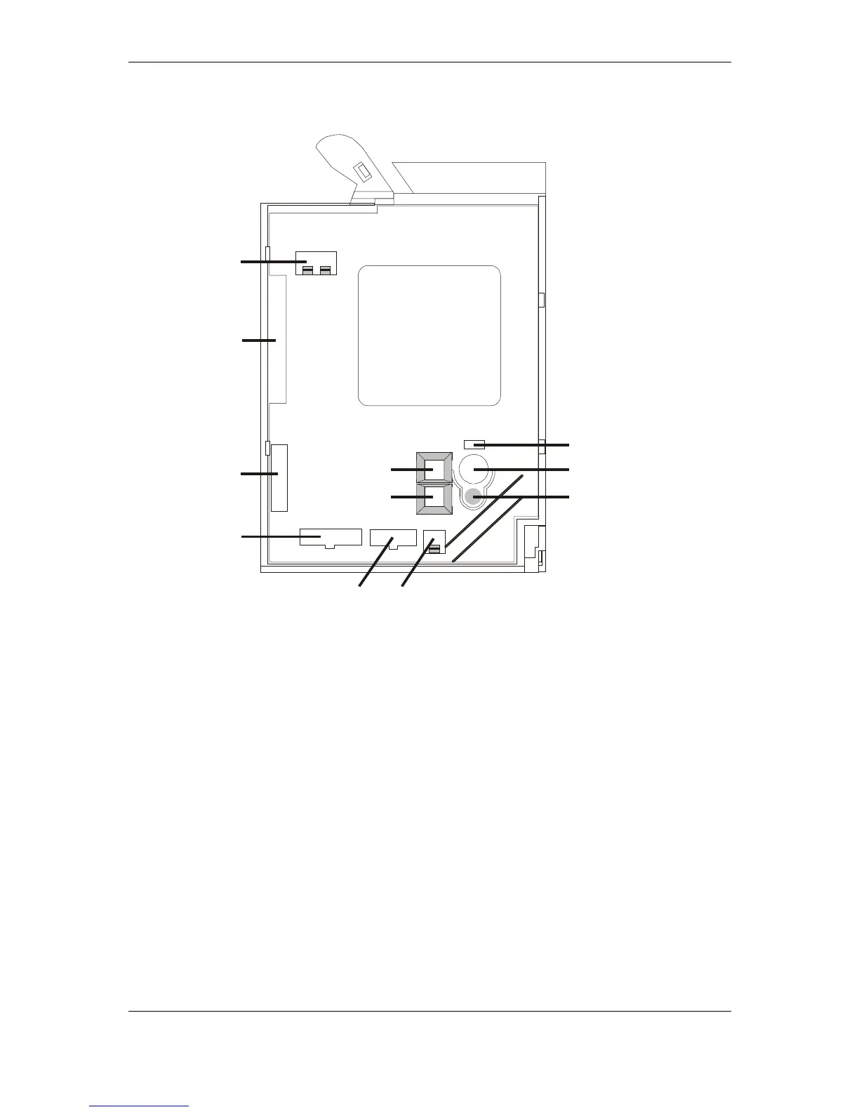
5) Electrical Connections
Figure 2: SR5 Connector Side
Table 1: SR5 Rear Cover Details.
1 DCE (Dual Coin Entry) See section 9).
2 Parallel Interface See section 10).
3 Sorter Override See section 12).
4 Routing Plug See section 13).
5 Serial interface (cctalk) See section 14).
6 Active Manifold See section 15).
7 Diagnostics See section 16).
8 Bank Select Switches See section 17).
9 LED Indicator
10 Token Select / Function Switch See section 18).
11 Program Button
1
2
3
4
56
8
9
10
11
7
 Loading...