SR5 Technical Manual TSP010.doc Issue 3.0 - October 2001
CONFIDENTIAL
Not to be disclosed without prior written permission from Money Controls
Page 40 of 50
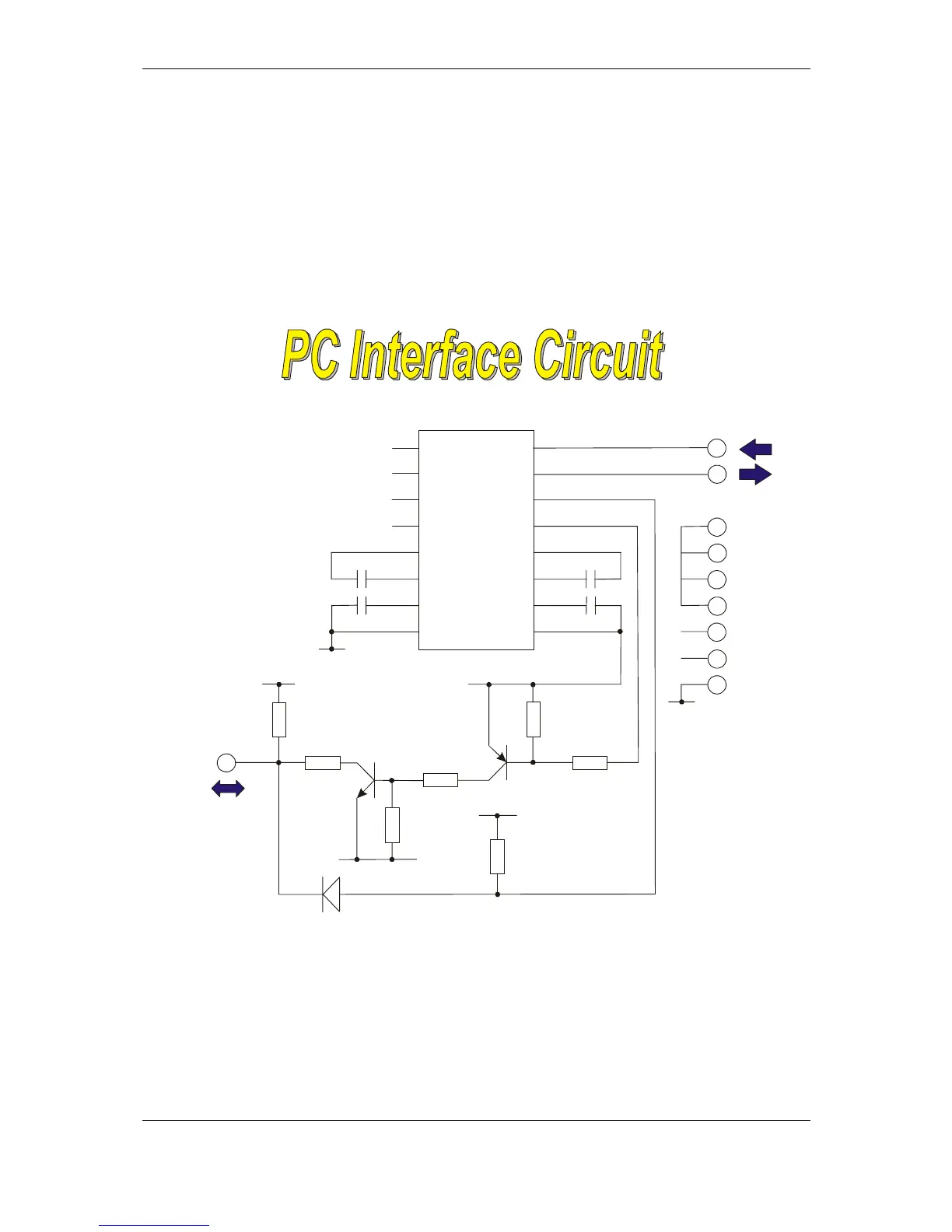
♦ Circuit 4 – cctalk PC Interface
The circuit below shows how to connect the 9-pin serial port of a PC to the
cctalk data bus. The only integrated circuit required is a Maxim level-shifter
which operates off a single +5V supply. Any small-signal diodes and transistors
can be used.
Figure 20: Circuit 4, cctalk PC Interface
MAX202E
100n
100n
100n
100K
100K
100K
10K
cctalk
DATA
+5V
or
+12V
47R
BC846
BAT54
0V
+5V
68K
68K
BCW68
+5V
100n
0V
8
13
3
2
4
1
6
8
7
9
5
0V
7
14
10
11
9
12
1
4
3
5
62
15
16
DTR
PC RX
PC TX
DCD
DSR
CTS
RTS
RI
GND
9-way
D-type
female