SECTION TWO – WIRING AND INSTALLATION
DS2000 USER’S MANUAL (rev.C)
2.15
• J7 connector
- Mating connector: female, 4 pins, crimp, supplied with the drive, model Molex 42816-
0412 (Moog code AK4990).
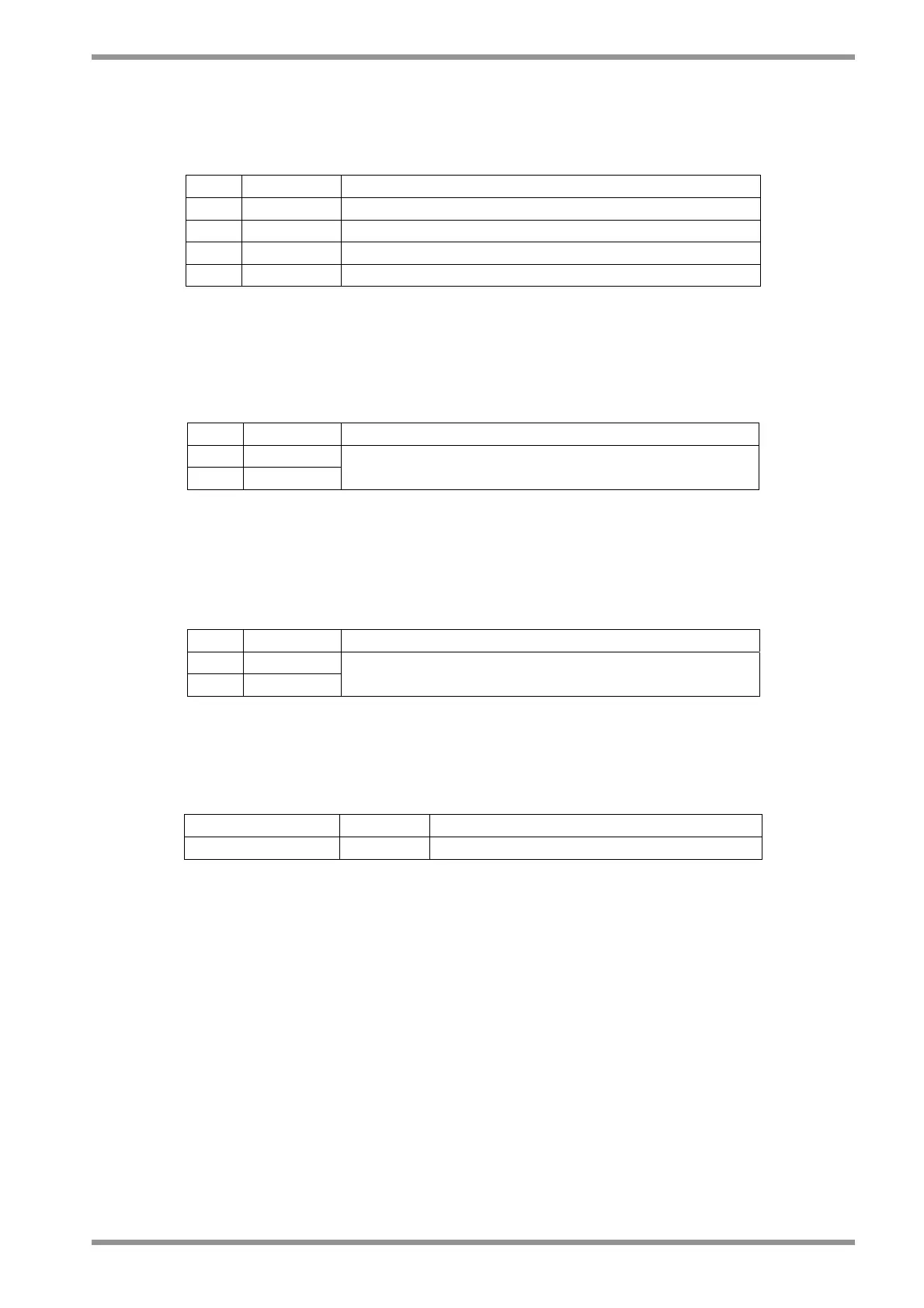
Pos. Name Function
1 ■ U2 Phase "U2", motor three-phase output
2 V2 Phase "V2", motor three-phase output
3 W2 Phase "W2", motor three-phase output
4 GND Motor ground (see also Ground screw)
Tab. 2.11 – J7 output motor power connector, size C
• J8 connector
- Mating connector: female, 2 pins, supplied with the drive, model Wago 231-102/026-
000 (Moog code AK4967).
Pos. Name Function
1 ■ +24V
2 0V (24V)
Auxiliary voltage inputs 24 V
dc
±10%, 2A
(pin 2 is connected to drive logic 0)
Tab. 2.12 – J8 auxiliary input power supply connector, size C
• J9 connector
- Mating connector: female, 2 pins, crimp, supplied with the drive, model Molex 42816-
0212 (Moog code AK4989).
Pos. Name Function
1 ■ -AT
2 +AT
DC BUS (see Application Engineer for details)
Tab. 2.13 – J9 DC BUS output connector, size C
• Ground screw
Use a lug for M5 screw.
Pos. Name Function
Ground screw GND Equipotential protection circuit.
Tab. 2.14 – Ground screw, size C
NOTE: In an especially noisy environment (from an electromagnetic point of view) it can
be useful to connect the motor ground (pin 4 of J7 connector) to the ground screw.