moog
MSD Servo Drive User Manual SERCOS II
21
[ Chapter 4 ]
Bit Explanation
Bit 11 Change bit of C3D (operation datum S-0-0013)
0 No change
1 Change
Bits 10, 9, 8 Current mode
0 0 0 Primary mode (defined by operation datum S-0-0032)
0 0 1 Secondary mode-1 (defined by operation datum S-0-0033)
0 1 0 Secondary mode-2 (defined by operation datum S-0-0034)
0 1 1 Secondary mode-3 (defined by operation datum S-0-0035)
1 0 0 Secondary mode-4 (defined by operation datum S-0-0284)
1 0 1 Secondary mode-5 (defined by operation datum S-0-0285)
1 1 0 Secondary mode-6 (defined by operation datum S-0-0286)
1 1 1 Secondary mode-7 (defined by operation datum S-0-0287)
Bit 7 Real-time status bit 2 (S-0-0306)
Bit 6 Real-time status bit 1 (S-0-0304)
Bit 5 Command change bit
0 No change of command acknowledgement
1 Change of command acknowledgement
Bit 4 Reserved
Bit 3 Status of setpoint transfer
0 The drive ignores the setpoints of the master, such as during drive-controlled
motion (homing, ..) or parameterizable delay times
1 The drive follows the setpoints of the master control system
Bit 2 “Fault“ in service channel
0 No fault
1 Fault in service channel, fault message in drive service INFO (S-0-0014)
Bit 1 “Busy“ bit
0 Step ended, ready for new step
1 Step being processed; new step not permitted
Bit 0 “AHS”
0/1 Service transport handshake of drive
Table 4.2 Drive status word (parameter S-0-0135)
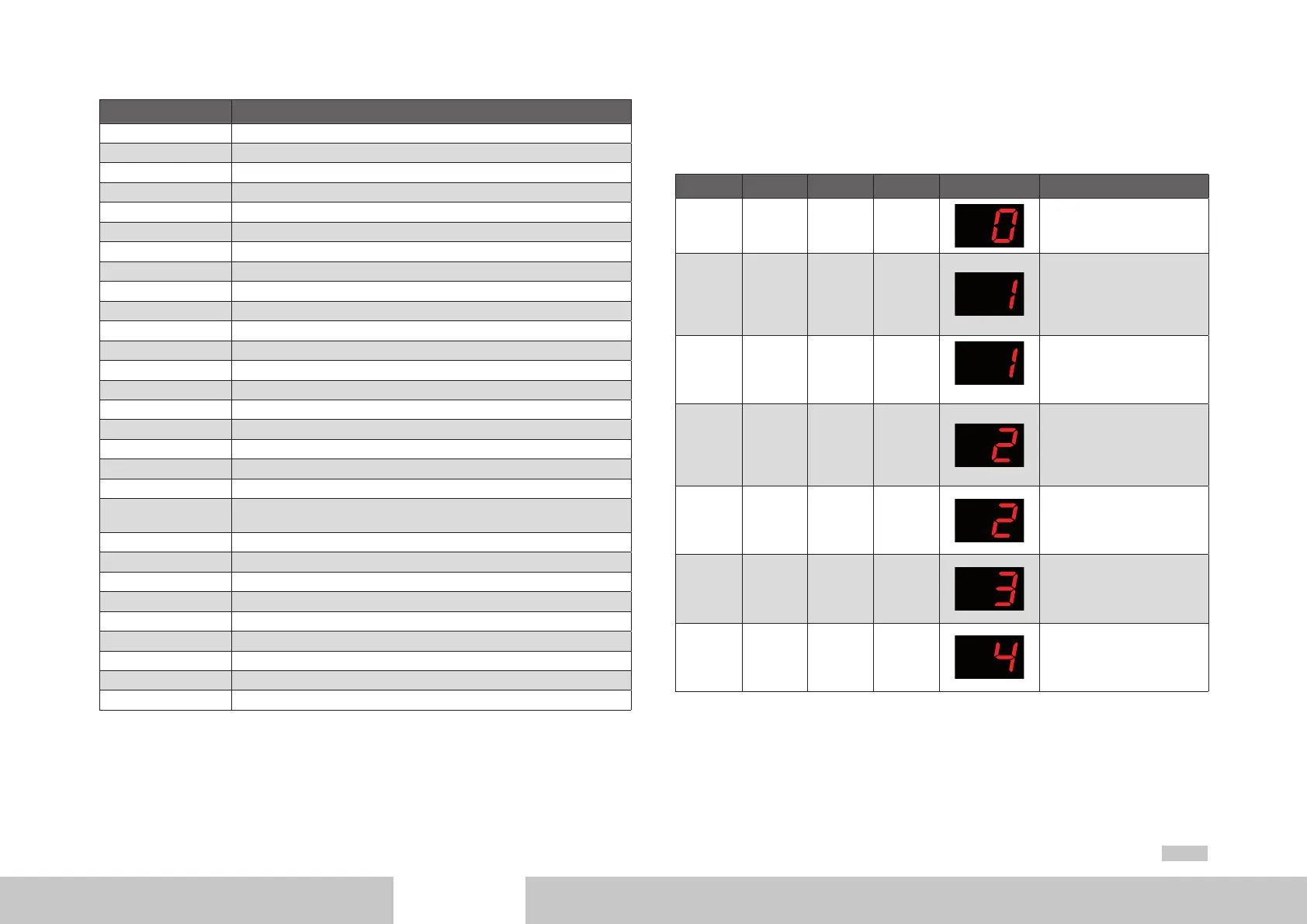
The system state of the drive is indicated on the display on the front panel of the unit.
Bits 15, 14, 13 and 3 of the SERCOS status word are mapped onto one of eight pos-
sible system states according the following table. The drive state machine (SERCOS) is
described in the following section.
Bit 15 Bit 14 Bit 13 Bit 3 Display readout System state designation
0 0 0 0
START
Drive in initialization phase
0 1 0 0
NOT READY FOR
START
Power stage without power,
no DC-link voltage, input STO
requested
0 1 0 0
NOT READY FOR
START
Power stage without power,
no DC-link voltage
1 0 0 0
STARTING LOCKOUT
POWER
Not enabled, DC-link voltag
Starting lockout Power e
present, input STO requested
1 0 0 0
STARTING LOCKOUT
Power stage without power,
not enabled, DC-link voltage
present
1 0 0 0
READY FOR START
Power stage without power,
enabled, DC-link voltage
present
1 0 0 0
ON ACTIVATE
Power stage (activate power
stage, motor commutation,
brake management)
Table 4.3 Mapping of bits 3, 13, 14 and 15 onto system state

 Loading...


