moog
MSD Servo Drive User Manual SERCOS II
24
A faulty configuration (e.g. unknown IDN) is refused when writing to S-0-0301,
S-0-0303, S-0-0305 or S-0-0307.
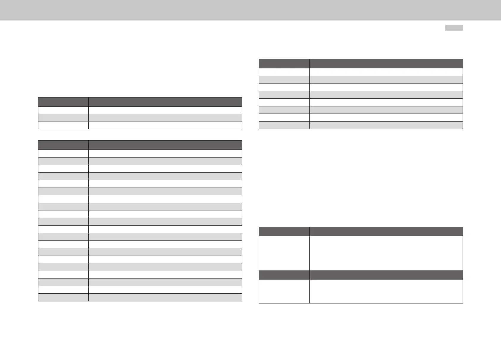
Only the parameters listed in P-0-3003 ”Real-time control bits” or P-0-3002 “Real-time
status bits” are permissible. Lists P-0-3002 and P-0-3003 are described in the following
tables.
Parameter Description
S-0-0405 Enable touchprobe 1
S-0-0406 Enable touchprobe 2 1
P-0-0141 Open-loop control of digital outputs via COM option
Table 4.6 List of parameters configurable as real-time control bits (P-0-3003)
Parameter Description
S-0-0011 State class 1 (device fault)
S-0-0012 State class 2 (device warnings)
S-0-0013 State class 3 (device state messages)
S-0-0014 Status word Sercos interface
P-0-0121 Status of the digital inputs
P-0-0143 Status of the digital outputs
S-0-0144 Signal status word
S-0-0179 Touchprobes 1 & 2 status
P-0-0239 Functional status of the digital inputs
S-0-0310 Warning threshold I2t motor exceeded
S-0-0311 Warning threshold heat sink temperature exceeded
S-0-0312 Warning threshold motor temperature exceeded
S-0-0330 Status speed setpoint reached
S-0-0331 Standstill message
S-0-0332 Speed threshold undershot
S-0-0333 Torque threshold exceeded
S-0-0334 Torque limit reached or exceeded
S-0-0335 Speed limit reached or exceeded
S-0-0336 Target position reached
S-0-0341 Status in track position
Table 4.7 List of parameters configurable as real-time status bits (P-0-3002)
Parameter Description
S-0-0401 Status touchprobe 1
S-0-0402 Status touchprobe 2
S-0-0403 Status actual position
S-0-0409 Touchprobe 1, positive edge recorded
S-0-0410 Touchprobe 1, negative edge recorded
S-0-0411 Touchprobe 2, positive edge recorded
S-0-0412 Touchprobe 2, negative edge recorded
S-0-0419 Status of setpoint transfer
Table 4.7 List of parameters configurable as real-time status bits (P-0-3002)
4.7 Signal control and status words
4.7.1 Signal control word (S-0-0145)
In the signal control word S-0-0145 signals can be transferred from the master control
system to the drive in real time. The signal control word can be configured for cyclic
transfer in the master data telegram (MDT). The signal control word is configured in
phase 2 and is activated at the transition to phase 3. A faulty configuration results in
a device fault and a refusal to switch to phase 3. The configuration parameters for the
signal control word are described in the following table.
S-0-0027 Configuration list, signal control word
This list contains all the parameter numbers included in the signal status word.
The sequence of parameter numbers in the list determines the significance
of the bits in the signal status word. The first parameter number in the list
defines bit 0; the last parameter number defines bit 15. Parameter S-0-0328
defines the bit number to be inserted into the signal status word from the
relevant parameter.
S-0-0329 Bit number assignment list, signal control word
In this configuration list the bit numbers of the parameters from S-0-0027
copied into the signal control word (S-0-0145) are programmed. The sequence
of the bit numbers in the list corresponds to the sequence of the signals in the
signal control word.
Table 4.8 Configuration parameters for the signal control word