moog
MSD Servo Drive User Manual SERCOS II
22
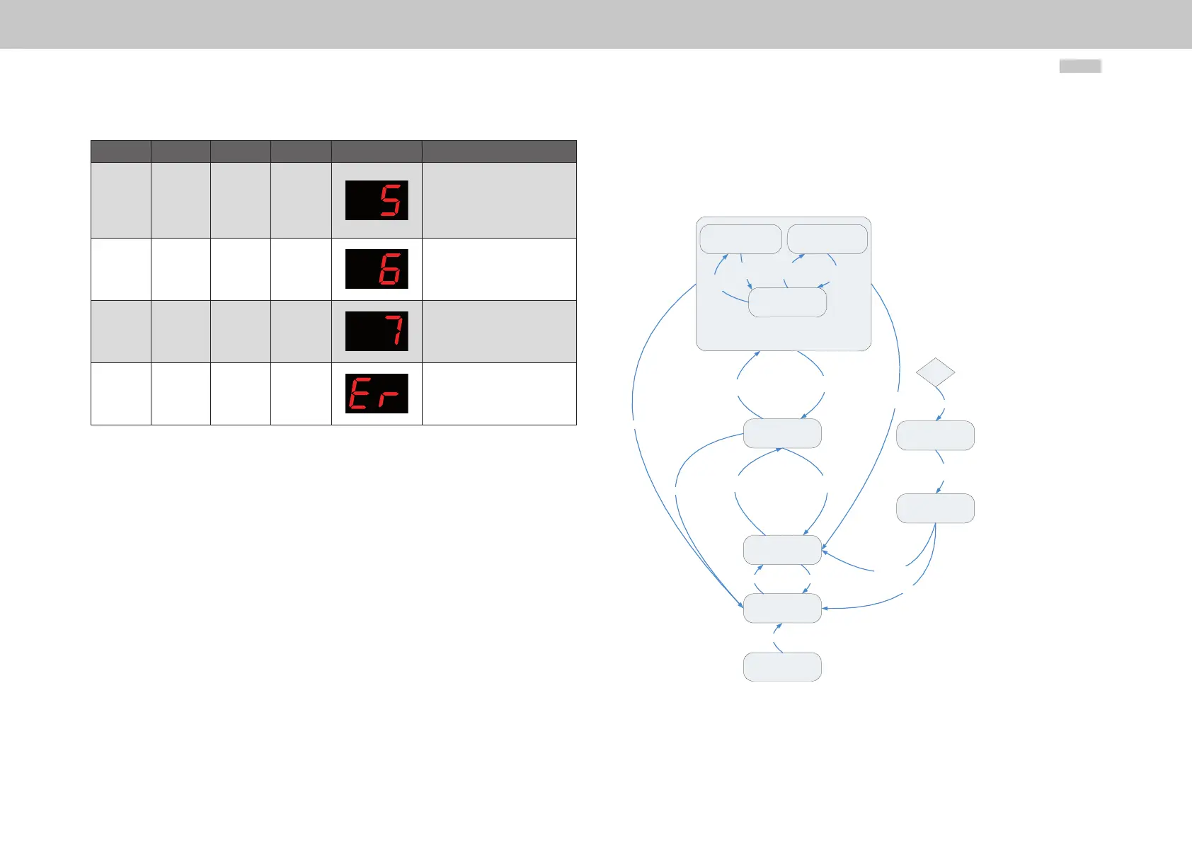
Bit 15 Bit 14 Bit 13 Bit 3 Display readout System state designation
1 1 0 1 / 0
LOOP CONTROL
ACTIVE
In loop control (support
for bit 3) Drive following
setpoints
1 1 0 0
QUICK-STOP ACTIVE
e.g. triggered via terminal,
drive no longer following
setpoints
1 1 1 0
FAULT RESPONSE
ACTIVE
Drive no longer following
setpoints
0 0 1 0
FAULT FAULT
Number and location
alternately displayed, motor
torque-free
Table 4.3 Mapping of bits 3, 13, 14 and 15 onto system state
4.5 Drive state machine
The system states and the possible state transitions are shown in the following diagram
and described in the following tables.
Figure 4.2
“System initialization
in progress”
System state 0
“Not ready for start”
System state 1
0 Start
“Starting lockout”
System state 2
1 UZK OK
2 enable Voltage
(Bit14=1 & ENPO=1)
“On”
System state 3
“Fault response active”
System state 7
“Fault”
System state 8
5 Disable Voltage
(Bit14=0 | ENPO=0)
3 Enable operation
(Bit 15=1 & Phase 4)
4 disable operation
(Bit 15=0)
5 Disable Voltage
(Bit14=0 | ENPO=0)
9 Fault Reset
6 (UZK off)
8 Fault Reaction
completed
6 (UZK off)
6 (UZK off)
6 (UZK off)
7 Fault
Fault
“Fault response active”
System state 5
“Active mode”
System state 5a
“Command execution”
System state 5c
“Drive halt”
System state 5b
Command
start
Command
end
Halt
(Bit 13=0)
Start
(Bit 13=1)
General system state machine (control via SERCOS)