moog
MSD Servo Drive User Manual SERCOS II
12
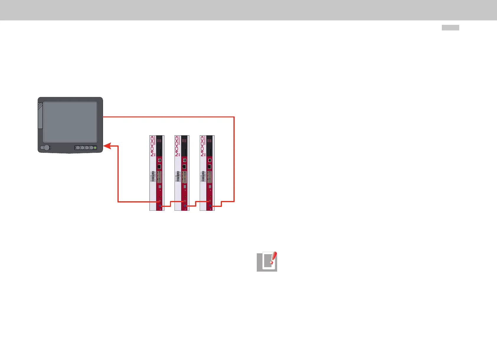
2.3 Connection of fibre-optic cables
The connection between the master (control) and the servo drives is made by fibre-optic
cables. This requires a loop architecture to be constructed, as illustrated in the following
diagram for three drive axes.
Figure 2.3
24
23
22
21
20
19
18
17
16
15
14
13
12
11
10
9
8
7
6
5
4
3
2
1
REL
REL
ISDSH
ISD06
ISD05
ISD04
ISD03
ISD02
ISD01
ISD00
+24 V
DGND
RSH
RSH
ENPO
OSD02
OSD01
OSD00
ISA1-
ISA1+
ISA0-
ISA0+
+24 V
DGND
ACHTUNG
WARNING
Kondensatorenent-
ladezeit > 3 min.
Betriebsanleitung
beachten!
Capacitor discharge
time > 3 min.
Pay attention to the
operation manual!
56
X
3
X
1
X
2
X
4
X
5
12345678
X
S
X
30
X
31
24
23
22
21
20
19
18
17
16
15
14
13
12
11
10
9
8
7
6
5
4
3
2
1
REL
REL
ISDSH
ISD06
ISD05
ISD04
ISD03
ISD02
ISD01
ISD00
+24 V
DGND
RSH
RSH
ENPO
OSD02
OSD01
OSD00
ISA1-
ISA1+
ISA0-
ISA0+
+24 V
DGND
ACHTUNG
WARNING
Kondensatorenent-
ladezeit > 3 min.
Betriebsanleitung
beachten!
Capacitor discharge
time > 3 min.
Pay attention to the
operation manual!
56
X
3
X
1
X
2
X
4
X
5
12345678
X
S
4
X
30
X
31
24
23
22
21
20
19
18
17
16
15
14
13
12
11
10
9
8
7
6
5
4
3
2
1
REL
REL
ISDSH
ISD06
ISD05
ISD04
ISD03
ISD02
ISD01
ISD00
+24 V
DGND
RSH
RSH
ENPO
OSD02
OSD01
OSD00
ISA1-
ISA1+
ISA0-
ISA0+
+24 V
DGND
ACHTUNG
WARNING
Kondensatorenent-
ladezeit > 3 min.
Betriebsanleitung
beachten!
Capacitor discharge
time > 3 min.
Pay attention to the
operation manual!
56
X
3
X
1
X
2
X
4
X
5
12345678
X
S
X
30
X
31
SERCOS
Master
Connection of fibre-optic cables
The fibre-optic loop starts and ends at the SERCOS master (control). The optical output
of the master is connected to the optical input of the first drive (X31). Its optical output
(X30) is connected to the input of the next drive, and so on. The output of the last drive
is connected to the optical input of the master. The SERCOS slave addresses are assigned
independently of their positions in the loop.
2.4 Hardware settings
2.4.1 Setting the transmission power of the SERCOS interface
By way of parameter P-0-3004 the transmission power of the fibre-optic transmitter can
be set. Entering a 0 corresponds to the lowest power and a 3 the highest. The following
values are intended as a guide:
0: <15 m
1: 15 .. 30 m
2: 30 .. 45 m
3: >45 or HCS
0: <15 m 1: 15 .. 30 m 2: 30..45 m 3: >45 or HCS
2.4.2 Setting the drive address via parameter
The drive address is set in parameter P-0-3000 (Drive address). EA drive address setting
or change made in this parameter only takes effect the next time the communication
phase changes from “0” to “1”. The drive address is independent of the position of the
drive in the SERCOS loop.
Drive address programming using pushbuttons and a display is in preparation.
2.4.3 Transfer rate of SERCOS interface
The transfer rate specified by the master is automatically detected by the drive, set ac-
cordingly and indicated in parameter S-0-0376: Baud rate, SERCOS interface.
NOTE: Baud rates of 2, 4, 8 and 16 MBaud are supported. Automatic baud
rate detection in the drive is implemented according to SERCOS Application
Note AN15 dated 2002/08/22.