moog
MSD Servo Drive User Manual SERCOS II
23
[ Chapter 4 ]
System
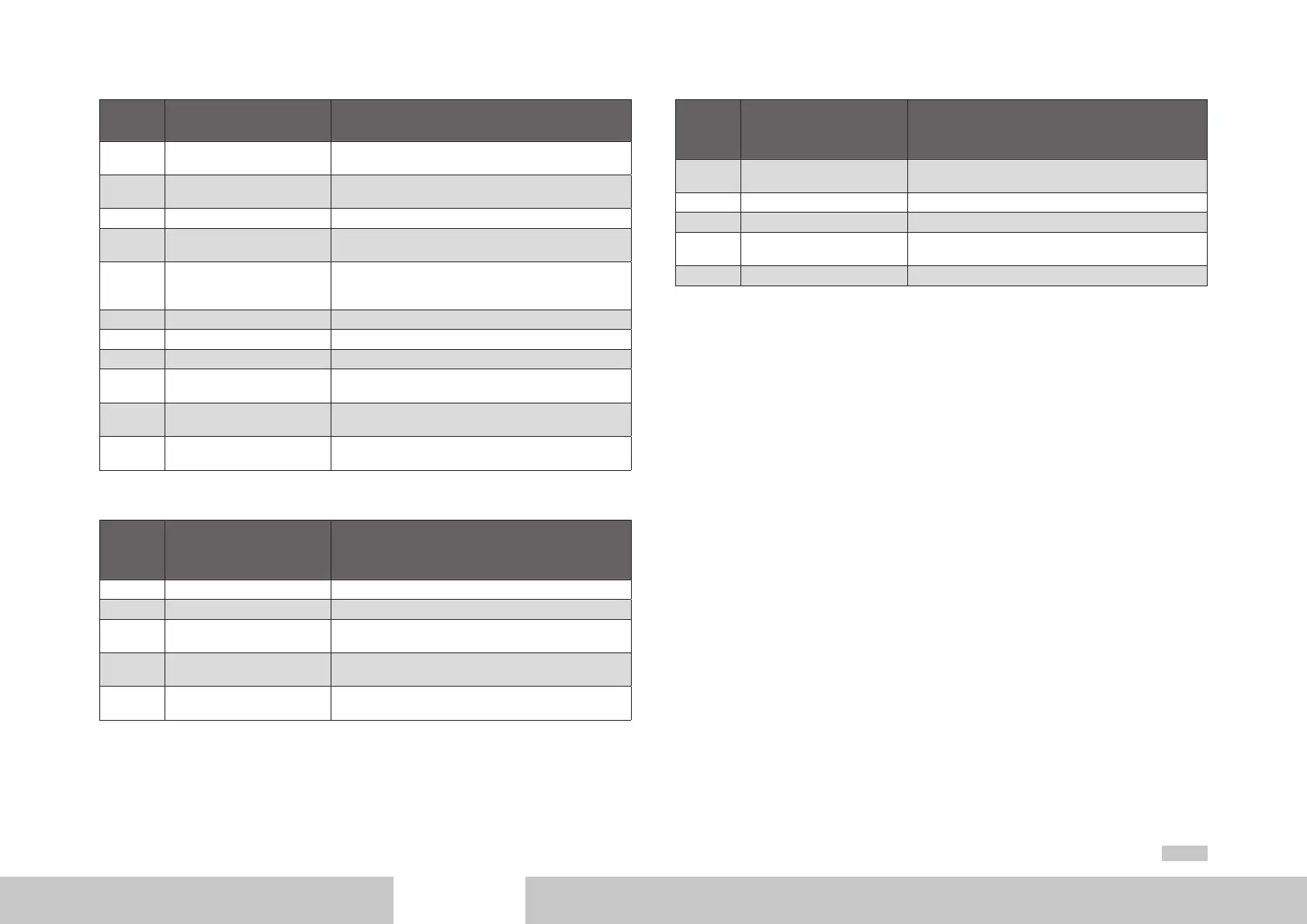
state
Designation Description
0 System initialization in
progress
Initialization after device reset (e.g. hardware, parameter
list, drive, ….)
1 Not ready for start Initialization complete, no mains power or DC-link volt-
age less than switch-on threshold
2 Starting lockout DC-link voltage greater than switch-on threshold
3 Ready for start Power stage enabled via hardware (ENPO and ISDSH)
and bit 14 in MDT
4 On Power stage is enabled (bit 15 in MDT = 1) (state is
automatically run through in open-loop control mode
via SERCOS)
5 Loop control active Current applied to motor; loop control active
5a Active mode The selected operation mode is active
5b Drive halt Drive halt active (shutdown via stop ramp)
5c Command execution A command with a movement sequence is active; set-
points from the SERCOS master are being ignored
7 Fault reaction active Fault reaction active; setpoints from the SERCOS master
are being ignored
8 Fault Drive in fault state; setpoints from SERCOS master being
ignored, drive torque-free
Table 4.4 Description of system state transitions
System
state
transition
Designation Description
0 START Initialization after boot-up complete
1 UZK OK DC-link voltage greater than switch-on threshold
2 ENABLE VOLTAGE Communication phase 4 active; bit 15 in SERCOS control
word = 1
3 ENABLE OPERATION Communication phase 4 active; bit 15 in SERCOS control
word = 1
4 DISABLE OPERATION Communication phase 4 active; input ENPO = 0 and/or
bit 14 in SERCOS control word = 0
Table 4.5 Description of system state transitions
System
state
transition
Designation Description
5 DISABLE VOLTAGE Communication phase 4 active; input ENPO = 0 and/or
bit 14 in SERCOS control word = 0
6 UZK OFF DC-link voltage less than switch-off threshold
7 Fault Fault event occurred (can occur in any system state)
8 FAULT REACTION ACTIVE The response configured for the fault is active (e.g. fault
stop ramp)
9 FAULT RESET Fault reset by command S-0-0099
Table 4.5 Description of system state transitions
4.6 Real-time control bits and real-time status bits
There are two configurable real-time bits in the MDT and the DT respectively. For
configurati¬on of these binary signals the following parameters are provided:
• S-0-0301, “Assignment IDN real-time control bit 1“
• S-0-0413, “IDN bit number real-time control bit 1“
• S-0-0303, “Assignment IDN real-time control bit 2“
• S-0-0414, “IDN bit number real-time control bit 2“
• S-0-0305, “Assignment IDN real-time status bit 1“
• S-0-0415, “IDN bit number real-time status bit 1“
• S-0-0307, “Assignment IDN real-time status bit 2“
• S-0-0416, “IDN bit number real-time status bit 2“
The real-time control bits and real-time status bits can be configured in phases 2, 3 and 4.
The assignment parameters contain the number of the parameter to configure for the
respective real-time bit.
With regard to configuration, note that the bit number must first be assigned (S-0-0413,
S-0-0414, S-0-0415, S-0-0416) before a corresponding IDN is assigned as the real-time
bit (S-0-0301, S-0-0303, S-0-0305, S-0-0307).