moog
MSD Servo Drive User Manual SERCOS II
13
[ Chapter 2 ]
2.5 Diagnostic LEDs
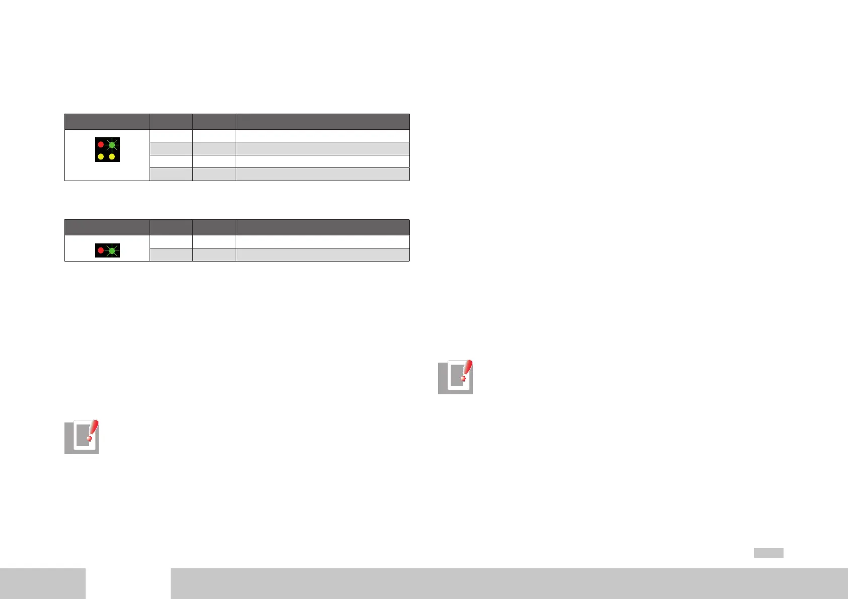
Hardware variant 1
LED Colour Meaning
H5
H4
H6 H7
H4 Red Distortion LED, fault on bus
H5 Green Status of SERCOS communication phase (flash code)
H6 Green Receiver LED, telegrams being received
H7 Green Transmitter LED, telegrams being sent
Hardware variant 2
LED Colour Meaning
H5
H4
H4 Red Distortion LED, fault on bus
H5 Green Status of SERCOS communication phase (flash code)
2.5.1 Use of the distortion LED
When you have set the drive address, you should check that there is an adequate optical
signal level at each station in the loop - that is, that the receiver is not being underload-
ed or overloaded. The optical level is checked by way of the distortion LED on the front
panel of the MSD Servo Drive (LED H4). Normally the distortion LED is unlit. To check
the optical level, check the distortion LEDs of all the drives in the loop, starting from the
transmitter output of the master, in the direction of the signal flow (see diagram under
“Connection of fibre-optic cables”). Check the distortion LEDs in the direction of the
light signal flow - that is, starting with the first drive in the loop. If its distortion LED is
unlit, move on to the next drive. Continue doing this until you reach the last drive, and
then the master (control).
NOTE: The distortion LED must not be lit or flashing.
A distortion LED lights up in the following cases:
• Defective fibre-optic cable to predecessor
• Unsupported transfer rate
• Incorrectly set transmission power
Procedure if distortion LED is lit:
Check the fibre-optic cable, with its connectors, from its physical predecessor in the
loop to the affected drive (see below). Compare the transfer rate of the master with the
supported drive baud rates. On the physical predecessor of the affected drive, check the
transmission power setting and adjust it as necessary by the DIP switches (HW variant 1)
or via parameter P-0-3004 (HW variant 2). In HW variant 1 parameter P-0-3004 only has
an influence if a higher transmission power is set on the DIP switches. That is to say, the
lowest transmission power set via the parameter or the DIP switches determines the actual
effective transmission power. It is not possible to upscale by way of the other channel.
2.5.2 Checking fibre-optic cables
If the specified transfer rate is supported and the transmission power is correctly set, but
still no communication takes place, the fibre-optic cable may be defective. In this case
the distortion LED will light. The cause of a defect in a fibre-optic cable may be mechani-
cal damage or poor assembly (bad connector fitting or the like). Defective fibre-optic
cables must be replaced.
NOTE: Fibre-optic transmission is sensitive to dirt contamination. Make sure
no dirt particles can penetrate the transmitter or receiver elements. This may
lead to transmission power and distortion problems which are difficult to
localize. Protect the elements during installation using the supplied sheaths
until the fibre-optic cables have been assembled.