moog
MSD Servo Drive User Manual SERCOS II
20
• P-0-0743 equal to 0
Position tracking error off. The drive switches on without correction and feeds
the position setpoint of the NC directly onto the drive. The drive moves to the
target position with a jerk as necessary. Major differences end in a speed tracking
error, depending on the parameter setting. A jerky axis motion is the consequence.
• P-0-0743 not equal to 0
Position tracking error on. The drive reads the target position of the master con-
trol system and moves under drive control to that position (position correction).
If the difference between the position specified by the control system and the
actual position is greater than the tracking error (P-0-0743), the drive switches to a
fault state, now without moving (no major axis motion). Otherwise the drive cor-
rects the difference with the slow jog rate (P-0-0168[1]) and the acceleration from
P-0-2242 (quick-stop). When the position has been reached, the drive switches to
state 5 and the drive follows the setpoints of the master control system (only now
is readiness signalled in the control word).
IMPORTANT:
With the scaling, the ramp setting which the system accesses must also be set correctly
and to reasonable values. This involves the parameters:
• P-0-2242 (Quick-stop). This is applied in the event of a fault, depending on the
configuration
• P-0-0168 (Jog, index 0: Jog rate rapid, index 1: Jog rate slow)
The position correction described above may take a very long time at a very slow jog
rate, or may even not take place at all, such as if P-0-0168[1] = 0. In this case the drive
would remain in system state 4, as the setpoint cannot be attained.
Bit 13: Drive HALT (feed hold)
The “Drive halt“ signal is state-controlled and low-active, meaning in response to a
“Drive halt = 0“ signal the drive is in the “Drive halt” state. The input signal is mapped
in the master control word, bit 13.
4.4 Drive status word
The drive status word is part of the drive telegram. It contains all the key status informa-
tion of the drive, e.g.:
• Readiness of control and power pack
• Drive fault
• Change bits state class 2 and 3
• Current mode
• Real-time status bits 1 and 2
• Status information for service channel
The drive status word is mapped in parameter S-0-0135. The precise structure of this
parameter is shown in the following table. The drive status word is transferred cyclically
to the control system with each drive telegram in the SERCOS cycle (see S-0-0002,
“SERCOS cycle time (TScyc)”). For diagnostic purposes, the drive status word can be
read via parameter S-0-0135, “Drive status word”.
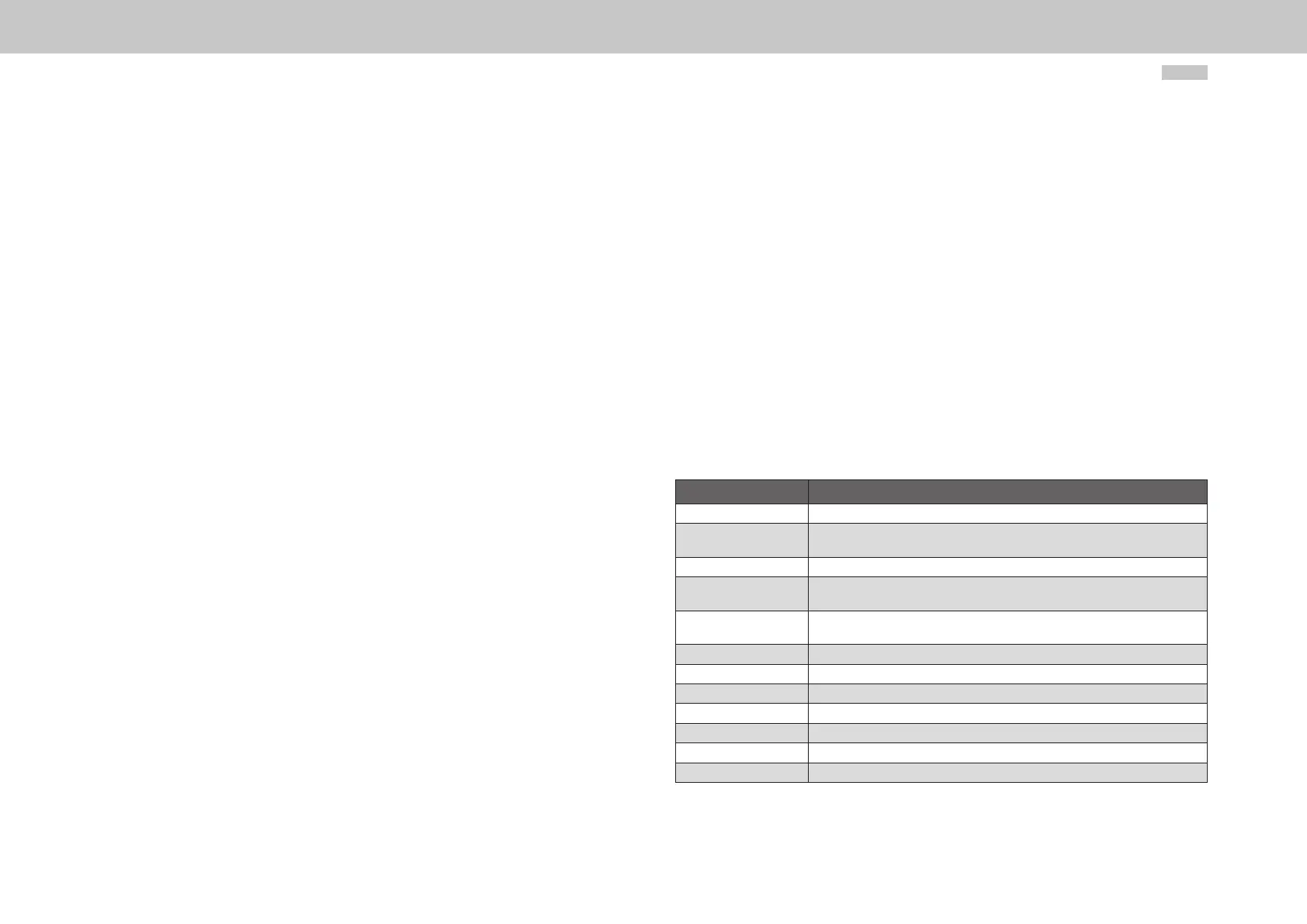
Bit Explanation
Bits 15, 14 „Ready“
0 0 Drive not ready to power up, as internal checks have not yet completed suc-
cessfully.
0 1 Drive ready to power up.
1 0 Drive control unit ready and power supply on, drive is torque-free and power
stage is disabled.
1 0 Drive control unit ready and power supply on, drive is torque-free and power
stage is disabled.
1 1 Drive ready, “Drive enable“ set and effective, power stage active.
Bit 13 Drive lockout fault in C1D (operation datum S-0-0011)
0 No fault
1 Drive locked due to a fault situation
Bit 12 Change bit of C2D (operation datum S-0-0012)
0 No change
1 Change
Table 4.2 Drive status word (parameter S-0-0135)