EN
English – 7
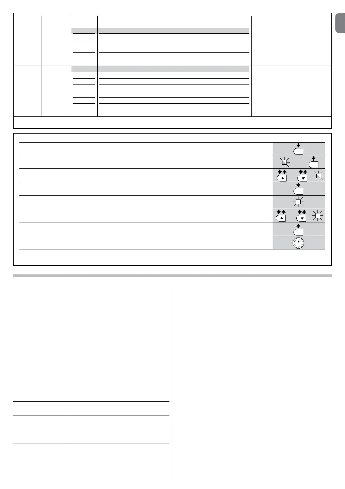
TABLE 8 – Programming procedure (second level functions)
01. Press and hold down the “Set” key for approx. 3 seconds.;
02. Release the key when LED “L1” starts flashing;
03. Press the “” or “” key to move the flashing LED to the LED representing the “input LED” of the parameter to be modified;
04. Press and hold the “Set” key through to completion of point 06;
05. Wait approx. 3 seconds, until the LED representing the current level of the parameter to be modified illuminates;
06. Press keys “” or “” to move the LED representing the value of the parameter;
07. Release the “Set” key;
08. Wait 10 seconds (maximum time) to exit the programming mode.
Note – During this procedure, points 03 to 07 need to be repeated when programming other parameters during the phase itself.
SET
SET
SET
SET
L1
or
or
3 s
10 s
5.3 - Special functions
5.3.1 - Function: “Move anyway”
This function allows the automation to be operated even when any of the safety
devices does not work correctly or is out of use.
The automation can be controlled in the “hold-to-run” mode. Proceed as follows:
01. Send a command to operate the gate using a transmitter or a key selector,
etc. If everything operates correctly, the gate will move normally, otherwise
proceed as follows;
02. within 3 seconds, activate the control again and keep it activated;
03.afterapproximately2seconds,thegatewillperformtherequiredmovement
in “hold-to-run” mode; i.e. the gate will continue to move only as long as
the control is activated.
If the safety devices do not operate, the flashing light flashes a few times to indi-
cate the kind of problem (see chapter 6 - Table 10).
5.3.2 - Function: “Maintenance warning”
Thisfunctionservestoindicatewhentheautomationrequiresmaintenance.
The maintenance warning signal is given by way of a lamp connected to the
S.C.A. (open gate light) output when this output is programmed as “Maintenan-
ce light”. The various warning lamp signals are shown in Table 9.
To program the limit value of the maintenance operations, see Table 8.
5.4 - Deleting the memory
To delete the control unit memory and restore all factory settings, proceed as
follows: press and hold keys “” and “” until leds L1 and L2 start flashing.
Table 9 - “Maintenance light”
Number of manoeuvres Signal
Light on for 2 seconds at the start of the opening
manoeuvre.
Light flashing for the entire duration of the manoeuvre.
Light flashing continuously.
Below 80% of the limit
Between 81% and
100% of the limit
Beyond 100% of the limit
Note – The factory settings are highlighted in grey.
L8 L1
L2
L3
L4
L5
L6
L7
L8
Manoeuvre 1 result (most recent)
Manoeuvre 2 result
Manoeuvre 3 result
Manoeuvre 4 result
Manoeuvre 5 result
Manoeuvre 6 result
Manoeuvre 7 result
Manoeuvre 8 result
The type of fault that has occurred in
the last 8 manoeuvres can be esta-
blished
See TABLE 12 – Fault log.
List of
faults
L7 L1
L2
L3
L4
L5
L6
L7
L8
500
1000
1500
2500
5000
10000
15000
20000
Controls the number of manoeuvres:
when this number is exceeded, the
control unit signals an automation
maintenancerequest;seeparagraph
5.3.2. – Maintenance warning.
Mainte-
nance
warning
 Loading...