EN
English – 9
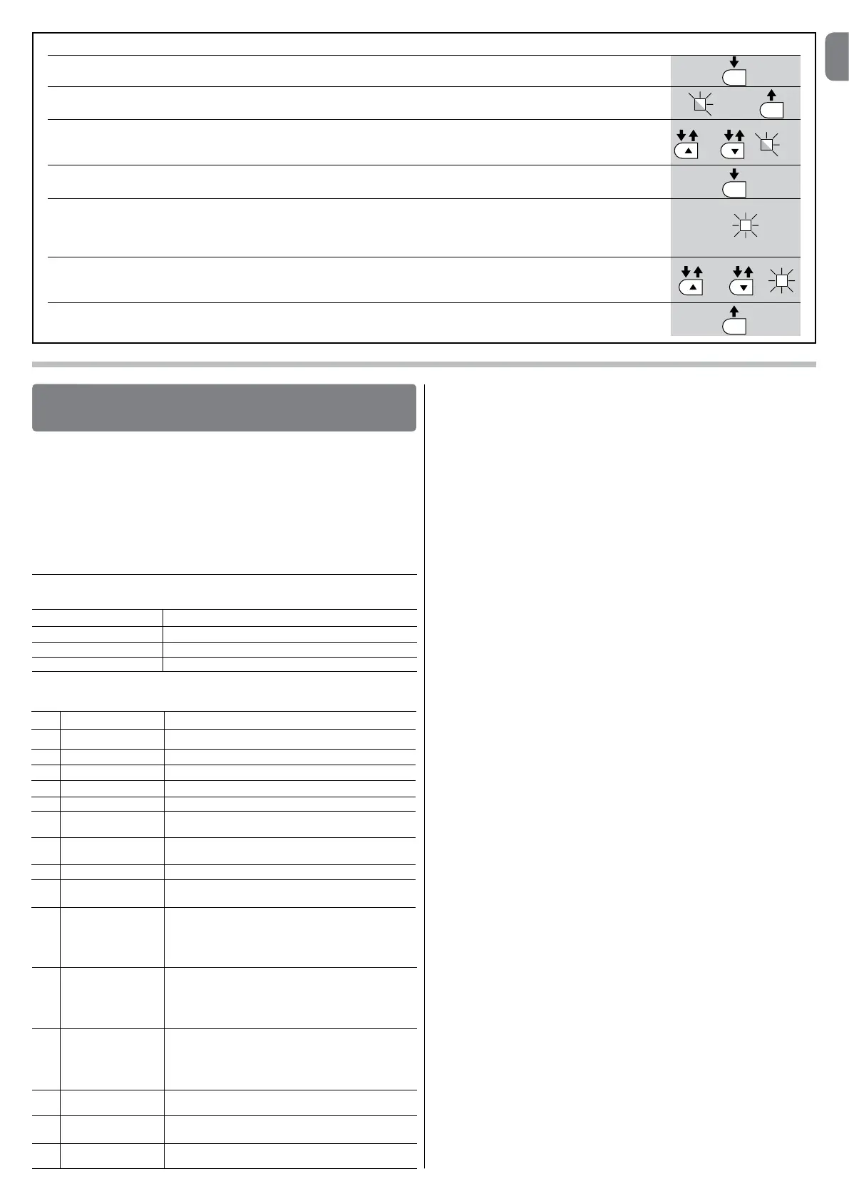
TABLE 12 - Fault log
01. Press and hold down the “Set” key for approx. 3 seconds;
02. Release the key when LED “L1” starts flashing;
03. Press keys “” or “” to move from the flashing LED to L8 LED (“input LED”) for the “Fault log” parameter;
04. Press and hold the “Set” key through to completion of point 06;
05. Wait approx. 3 seconds until the LEDs representing the levels corresponding to the manoeuvres with faults illuminate.
The LED L1 indicates the result of the most recent manoeuvre while L8 indicates the eighth-to-last manoeuvre.
If the LED is on this means that a fault has occurred; if the LED is off, everything is normal;
06. Press keys “” and “”toselecttherequiredmanoeuvre:thecorrespondingLEDperformsanumberofflashesequal
to those normally performed by the flashing light;
07. Release the “Set” key.
SET
SET
SET
SET
L1
or
and
3 s
The following optional accessories are available for the control unit MC824H:
SMXI, OXI family receivers, Oview programmer, the Solemyo solar energy panel
and the PS324 buffer battery.
7.1 - Connecting a radio receiver
The control unit has a connector for connecting radio receivers (optional accesso-
ries) belonging to the SMXI and OXI families. To connect a receiver, disconnect
power from the control unit and proceed as shown in fig. 8. Table 13 and Table
14 show the commands corresponding to the outputs on the control unit.
FURTHER DETAILS
7
Table 13
SMXI / SMXIS or OXI / OXIFM / OXIT / OXITFM in mode I or Mode II
“S.S.” (Step by Step) command
“Partial opening 1” command
“Open” command
“Close” command
Output no. 1
Output no. 2
Output no. 3
Output no. 4
1 Step by step
2 Partial opening 1
3 Open
4 Close
5 Stop
6 Apartment block
Step by Step
7 Step by Step
high priority
8 Partial open 2
9 Partial open 3
10 Open and block
automation
11 Close and block
automation
12 Block automation
13 Release
automation
14 Courtesy light
timer on
15 Courtesy light
on-off
Table 14
OXI / OXIFM /OXIT / OXITFM in extended mode II
No. Command Description
“S.S.” (Step by Step) command
“Partial opening 1” command
“Open” command
“Close” command
Stops manoeuvre
Apartment block control
Gives command even when automation is blocked
or commands are in progress
Partial open (Opening of leaf M2 to 1/2 of normal opening)
Partial open (Opening of two leafs to 1/2 of normal opening)
It causes an opening manoeuvre, after which the automa-
tion is blocked; the control unit accepts no further com-
mands with the exception of “Step by step high priority”,
“Release” automation and (from Oview only) the comman-
ds “Release and close” and “Release and open”
It causes a closure manoeuvre, after which the automation
is blocked; the control unit accepts no further commands
with the exception of “Step by step high priority”, “Release”
automation and (from Oview only) the commands “Release
and close” and “Release and open”
It causes the manoeuvre to stop and the automation to
block; the control unit accepts no further commands with
the exception of “Step by step high priority”, “Release”
au to mation and (from Oview only ) the commands “Relea-
se and close” and “Release and open”.
It causes the automation to be released and normal ope-
ration to resume
The Courtesy light comes on with timed turning off
The Courtesy light turns on and off in step-by-step mode
7.2 - Connecting Oview programming unit
Connector BusT4 on the control unit enables connection of the programming
unit Oview which enables complete and rapid management of installation,
maintenance and troubleshooting of any malfunctions of the whole automation
system. To gain access to the connector, proceed as shown in fig. 9 and con-
nect the connector to its seat. The Oview can be connected simultaneously to
a number of control units (up to 5 without any particular precautions, up to 60
following the relevant warnings) and can remain connected to the control unit
during normal operation of the automation. In this case a specific “user” menu
enables commands to be sent directly to the control unit. It is also possible to
update the firmware. If an OXI family radio receiver is present in the control unit,
Oview enables access to the parameters of the transmitters memorised in this
receiver.
Further information is available in the instruction manual and the “Opera system
book” manual.
7.3 - Connecting the Solemyo solar energy system
To connect the solar energy system see fig. 10.
IMPORTANT! – When the automation is powered by the “Solemyo”
system, it MUST NOT BE POWERED at the same time from the elec-
trical mains.
For other information, refer to the relevant instruction manual.
7.4 - Connecting model PS324 buffer battery
To connect the buffer battery, see fig. 10. For other information, refer to the
relevant instruction manual.
3 s
L8
 Loading...