External
Input
NOTES:
Cleared
by
TCR3
Write
Read
Interrupt
Software
Functions
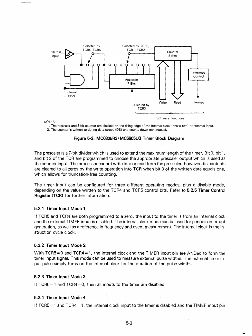
1.
The prescaler and 8-bit counter are clocked on the rising edge of the internal clock (phase two) or external input.
2.
The counter
is
written
to
during data strobe
(OS)
and counts down continuously.
Figure 5-2. MC6805R3/ MC6805U3 Timer Block Diagram
The
prescaler
is
a 7-bit divider which is used to extend the maximum length
of
the timer. Bit
0,
bit
1,
and bit 2
of
the
TCR
are
programmed to choose the appropriate prescaler
output
which
is
used
as
the counter input. The processor cannot write into or
read
from the prescaler; however, its contents
are
cleared to all zeros by the write operation into
TCR
when bit 3
of
the written data equals one,
which
allows for truncation-free counting.
The timer input can
be
configured for three different operating modes, plus a disable mode,
depending on the
value written
to
the TCR4 and TCR5 control bits. Refer to 5.2.5 Timer Control
Register (TCR) for further information.
5.2.1 Timer
Input Mode 1
If
TCR5 and TCR4
are
both programmed
to
a zero, the input
to
the timer
is
from
an
internal clock
and the external TIMER input
is
disabled. The internal clock mode
can
be
used for periodic interrupt
generation,
as
well
as
a reference
in
frequency and event measurement. The internal clock
is
the in-
struction cycle clock.
5.2.2 Timer Input Mode 2
With
TCR5= 0 and TCR4=
1,
the internal clock and the TIMER input pin are ANDed
to
form the
timer input
Signal. This mode can
be
used to measure external pulse widths. The external timer in-
put
pulse simply turns on the internal clock for the duration
of
the pulse widths.
5.2.3 Timer
Input Mode 3
If
TCR5= 1 and TCR4= 0, then
all
inputs to the timer
are
disabled.
5.2.4 Timer Input Mode 4
If
TCR5= 1 and TCR4= 1, the internal clock input
to
the timer
is
disabled and the TIMER input pin
5-3
 Loading...

