SECTION 7
RESET,
CLOCK,
AND
INTERRUPT STRUCTURE
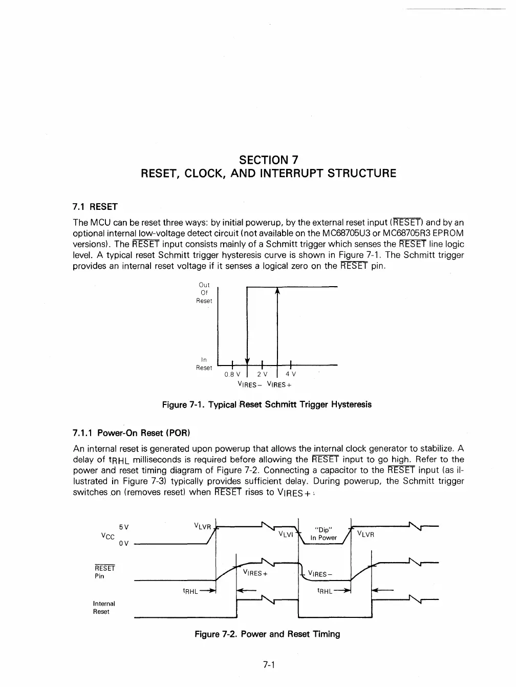
7.1 RESET
The MCU
can
be
reset three ways: by initial powerup, by the external reset input
(RESET)
and by
an
optional internal low-voltage detect circuit (not available
on
the MC68705U3 or MC68705R3
EPROM
versions). The
RESET
input consists mainly
of
a Schmitt trigger which senses the
mTI
line logic
level.
A typical reset Schmitt trigger hysteresis curve
is
shown
in
Figure
7-1.
The Schmitt trigger
provides
an
internal reset voltage if it senses a logical zero
on
the
RESET
pin.
Out
Of
Reset
In
11
,
Reset
1.....--+--+--1-+-"...----
0.8
V 2 V 4 V
VIRES-
VIRES+
Figure 7-1. Typical
;Reset
Schmitt Trigger Hysteresis
7.1.1 Power-On Reset
(POR)
An internal reset
is
generated upon powerup that allows the internal clock generator to stabilize. A
delay
of
tRHL milliseconds
is
required before allowing the
RESET
input to go high. Refer to the
power and reset timing diagram
of
Figure 7-2. Connecting a capacitor to the
RESET
input
(as
il-
lustrated
in
Figure
7-3)
typically provides sufficient delay. During powerup, the Schmitt trigger
switches
.on
(removes
reset)
when
RESET
rises
to VIRES +,
Vee
RESET
Pin
Internal
Reset
5V
ov
-------
Figure 7-2. Power and Reset Timing
7-1
 Loading...

