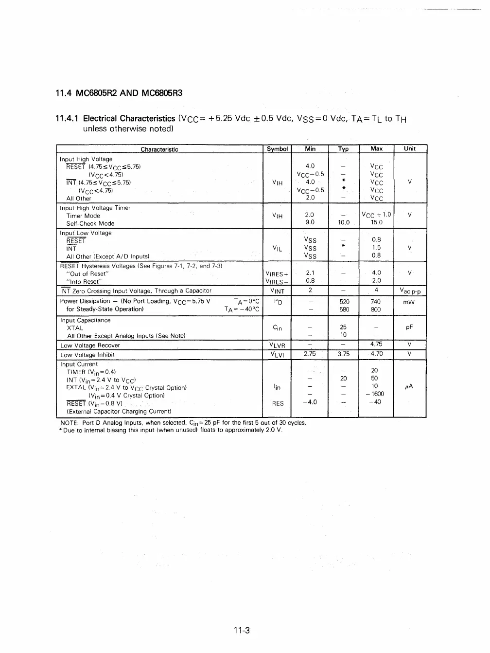
11.4 MC6805R2
AND
MC6805R3
11.4.1 Electrical Characteristics (VCC=
+5.25
Vdc ±O.5 Vdc,
VSS=O
Vdc,
TA=TL
to
TH
unless otherwise noted)
Characteristic
Symbol
Min
Input High Voltage
RESET
(4.75sVCCs5.75)
4.0
(VCC<4.75)
VCC-05
INT
(4.75sVCCs5.75)
VIH
4.0
(VCC<4.75)
VCC-0.5
All Other
2.0
Input
High Voltage Timer
Timer Mode
VIH
2.0
Self-Check
Mode
9.0
Input Low Voltage
RESET
VSS
INT VIL
VSS
All Other (Except
AID
Inputs) VSS
RESET
Hysteresis Voltages (See Figures 7-1, 7-2, and
7-3)
"Out
of Reset"
VIRES+
2.1
"I
nto Reset"
VIRES-
O.S
INT Zero Crossing Input Voltage, Through a Capacitor
VINT
2
Power Dissipation - (No Port Loading, V
CC
= 5.75 V
TA=O°C
PD
-
for Steady-State Operation)
TA=
-40°C
-
Input Capacitance
XTAL
Cin
-
All Other Except Analog Inputs (See Note)
-
Low Voltage Recover VLVR
-
Low Voltage Inhibit VLVI
2.75
Input Current
TIMER
(Vin=O.4)
-
INT
(Vin=2.4
V to
VCC)
-
EXT
AL
(Vin = 2.4 V
to
V
CC
Crystal Option)
lin
-
(Vin=O.4
V Crystal Option)
-
RESET
(Vin=O.S
V)
IRES
-4.0
(External Capacitor Charging Current)
NOTE: Port
D Analog Inputs, when selected,
Cin
=
25
pF
for the first 5 out
of
30
cycles.
* Due
to
internal biasing this input (when unused) floats
to
approximately 2.0
V.
11-3
Typ
Max
Unit
-
VCC
-
VCC
*
VCC
V
*
VCC
-
VCC
-
VCC
+ 1.0
V
10.0
15.0
-
O.S
*
1.5 V
-
O.S
-
4.0 V
-
2.0
-
4
Vac p-p
520
740
mW
5S0
SOO
25
-
pF
10
-
-
4.75
V
3.75
4.70 V
-
20
20
50
-
10
p,A
-
-1600
-
-40
 Loading...

