prescaler; however, the prescaler
is
set
to
all
ones by a write operation to TCR,
b3
(when bit 3 of the
written data
equals one), which allows for truncation-free counting.
5.3.2
MOR
Controlled Mode
The
MOR
controlled mode of the timer
is
selected when the TOPT (timer option) bit
(b6)
in
the
MOR
is
programmed to a logic one
to
emulate the MC6805R2 mask-programmable prescaler and
timer
clock source. The timer circuits
are
the
same
as
described above, however, the timer control
register
(TCR)
is
configured differently,
as
discussed below.
The logic level for the functions of bits
bO,
bl,
b2,
and
b5
in
the
TCR
are
all
determined at the time
of
EPROM
programming. They
are
controlled by corresponding bits within the mask option register
(MOR, $F38l. The value programmed into
MOR
bits
bO,
bl,
b2,
and
b5
controls the prescaler divi-
sion and the timer clock
selection. Bit
b4
(TIE)
is
set to a logic one
in
the
MOR
controlled mode
(when
read
by software, these five
TCR
bits always
read
as
logic ones). As
in
the software program-
mable configuration, the TIM
(b6)
and
TIR
(b7)
bits of the
TCR
are
controlled by the counter and
software
as
described above. Bit
b3
of
the
TCR
(in the
MOR
controlled mode) for the
MC68705R31
MC68705U3 always
reads
as
a logic zero and
can
be
written to a logic one to clear the prescaler;
however, for the MC68705R5/MC68705U5 bit
b3
is
set to a logic one and when
read
by software
always
reads
as
a logic one. The
MOR
controlled mode
is
designed
to
exactly emulate the
MC6805R2 which
has
only TIM, TIR, and
PSC
in
the
TCR
and
has
the prescaler options defined
as
manufacturing mask options.
5.3.3 Timer
Control Register (TCR)
The configuration
of
the
TCR
is
determined by the logic level
of
bit 6 (timer option, TOPT)
in
the
mask option register
(MORl. Two configurations
of
the
TCR
are
shown below, one for TOPT = 1
and the other for
TOPT =
O.
TOPT = 1 configures the
TCR
to emulate the
MC6805R2.
When
TOPT =
0,
it provides software control of the
TCR.
When TOPT =
1,
the prescaler
"mask"
options
are
user programmable via the MOR. A description of
each
TCR
bit
is
provided below (also
see
Figures
5-3
and 5-4).
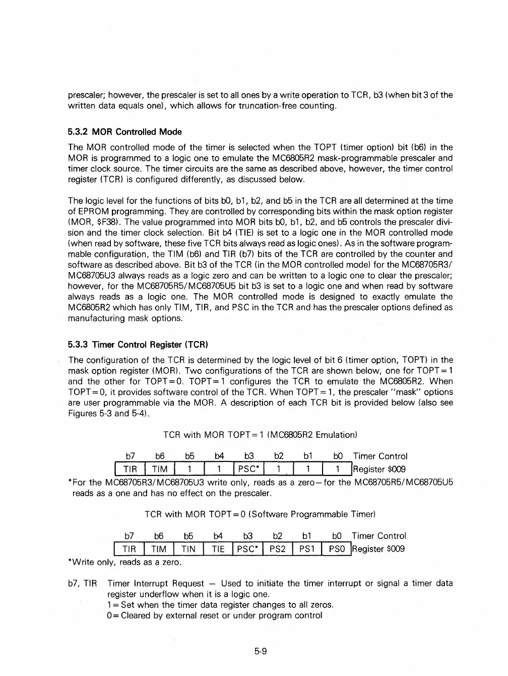
TCR
with
MOR
TOPT= 1 (MC6805R2 Emulation)
b7 b6 b5
b4
b3
b2
bl
bO
Timer Control
TIR
TIM ! PSC* ! 1 !Register
$009
*For the MC68705R3/MC68705U3 write only,
reads
as
a
zero-for
the MC68705R5/MC68705U5
reads
as
a one and
has
no effect
on
the prescaler.
TCR
with
MOR
TOPT = 0 (Software Programmable Timer)
b7
b6
b5
b4
b3
b2
bl
bO
Timer Control
"""-T-I
R~-T-I-M"""'T"'-T-I
N~-TI-E"""'T"'I
-PS-C-*"""I-P-S-2--r--
P
-
S
-
l
"""--PS-0-"IRegister
$009
*Write only,
reads
as
a zero.
b7,
TIR
Timer Interrupt Request -
Used
to
initiate the timer interrupt or signal a timer data
register
underflow when it
is
a logic one.
1 = Set when the timer data register changes to
all
zeros.
0=
Cleared
by
external reset or under program control
5-9
 Loading...

