Pin2
1.01'F
....
-
____
-+-4
Typical
POR
Delay
Capacitor
* Disable LVI
7.1.2 External Reset Input
Charging
Current
Source
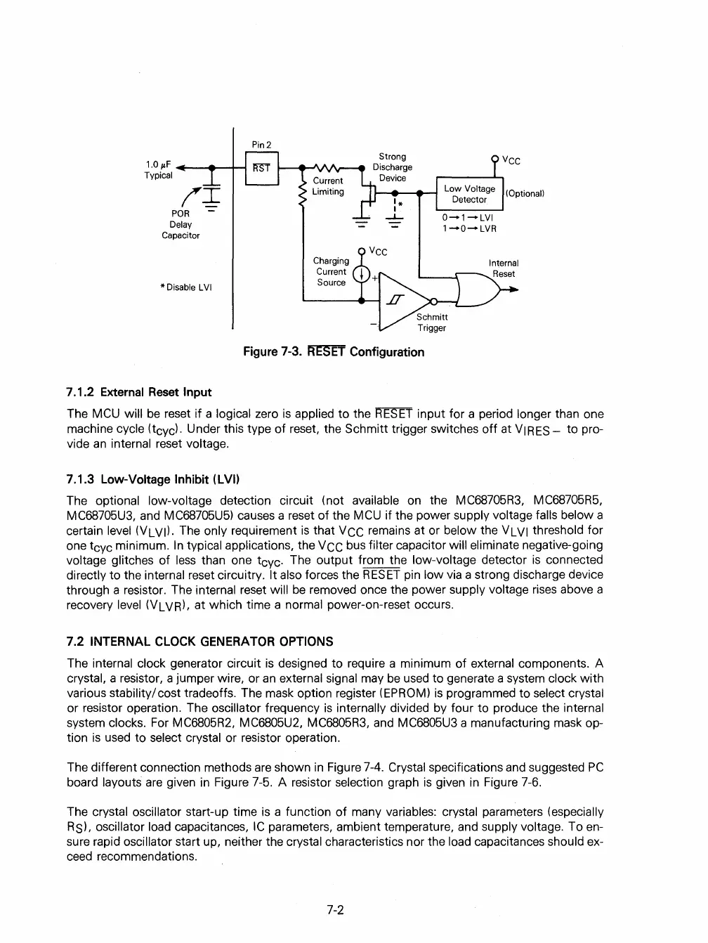
Figure 7-3.
FfESET
Configuration
(Optional)
The MCU will
be
reset
if
a logical zero
is
applied
to
the
RESET
input for a period longer than one
machine cycle
(tcycl. Under this type
of
reset, the Schmitt trigger switches
off
at
VIRES-
to
pro-
vide
an
internal reset voltage.
7.1.3 Low-Voltage Inhibit (LVI)
The optional low-voltage detection circuit (not available on the MC68705R3, MC68705R5,
MC68705U3,
and MC68705U5) causes a reset
of
the MCU
if
the power supply voltage falls below a
certain
level (VLVI). The only requirement
is
that VCC remains at or below the VLVI threshold for
one tcyc minimum.
In
typical applications, the
VCC
bus filter capacitor will eliminate negative-going
voltage glitches
of
less
than one tcyc. The
output
from the low-voltage detector
is
connected
directly
to
the internal reset circuitry. It also forces the
RESET
pin
low
via a strong discharge device
through a resistor. The
internal reset will
be
removed once the power supply voltage rises above a
recovery
level (VLVR), at which time a normal power-on-reset occurs.
7.2
INTERNAL CLOCK GENERATOR OPTIONS
The internal clock generator circuit
is
designed
to
require a minimum
of
external components. A
crystal, a resistor, a jumper wire, or
an
external signal may
be
used to generate a system clock
with
various stability/ cost tradeoffs. The mask option register (EPROM)
is
programmed
to
select crystal
or
resistor operation. The oscillator frequency
is
internally divided by four
to
produce the internal
system clocks. For MC6805R2, MC6805U2, MC6805R3, and MC6805U3 a manufacturing mask op-
tion
is
used
to
select crystal or resistor operation.
The different connection methods are shown
in
Figure 7-4. Crystal speCifications and suggested
PC
board layouts
are
given in Figure 7-5. A resistor selection graph
is
given in Figure 7-6.
The
crystal oscillator start-up time
is
a function
of
many variables: crystal parameters (especially
RS), oscillator load
capacitances,
IC
parameters, ambient temperature, and supply voltage. To en-
sure rapid
oscillator start up, neither the crystal characteristics nor the load capacitances should ex-
ceed recommendations.
7-2
 Loading...

