(See Note 2)
c=l
CL
External
~CIOCk
Input
NOTES:
I
6
XTAL
MCU
5
EXTAL
(Crystal Option,
See
Note
1)
6 XTAL
MCU
5 EXTAL (Crystal Option,
See
Note
1)
External Clock
6
XTAL
MCU
5
EXTAL
mc
Option,
See
Note
1)
Approximately 25% to 50% Accuracy
Typical
tcyc=
1.25
p's
External Jumper
_'HH
___
6 ... XTAL
R
(See
Figure 7-5) 5 EXTAL
MCU
(RC
Option,
See
Note
1)
No
Connection
Approximately 10% to 25% Accuracy
(Excludes Resistor Tolerance)
External Resistor
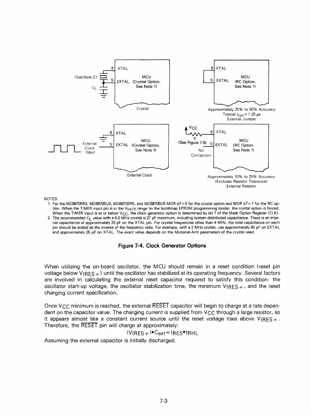
1.
For the MC68705R3, MC68705U3, MC68705R5, and MC68705U5 MOR
b7
= 0 for the crystal option and
MOR
b7
= 1 for the
RC
op-
tion. When the
TIMER input pin
is
in the VIHTP range (in the bootstrap
EPROM
programming mode), the crystal option
is
forced.
When the
TIMER input
is
at or below VCC, the clock generator option
is
determined by bit 7 of the Mask Option Register (CLK)'
2.
The recommended
CL
value
with
a 4.0 MHz crystal
is
27
pF
maximum, including system distributed capacitance. There
is
an
inter-
nal
capacitance
of
approximately
25
pF
on the XTAL pin. For crystal frequencies other than 4 MHz, the total capacitance on each
pin should
be scaled
as
the inverse
of
the frequency ratio. For example, with a 2 MHz crystal, use approximately
50
pF
on EXTAL
and approximately
25
pF
on XT AL. The exact value depends
on
the Motional-Arm parameters
of
the crystal used.
Figure
7-4.
Clock
Generator
Options
When utilizing the on-board oscillator, the MCU should remain
in
a reset condition (reset pin
voltage below
VIRES
+)
until the oscillator
has
stabilized at its operating frequency. Several factors
are
involved
in
calculating the external reset capacitor required
to
satisfy this condition: the
oscillator start-up voltage, the oscillator stabilization time, the minimum
VIRES
+,
and
the reset
charging current specification.
Once
VCC
minimum
is
reached, the external
RESET
capacitor will begin to charge at a rate depen-
dent
on
the capacitor value. The charging current
is
supplied from
VCC
through a large resistor,
so
it
appears almost like a constant current source until the reset voltage
rises
above
VIRES
+.
Therefore, the
RESET
pin will charge at approximately:
(VIRES
+ )eCext= IRESetRHL
Assuming the external capacitor
is
initially discharged.
7-3
 Loading...

