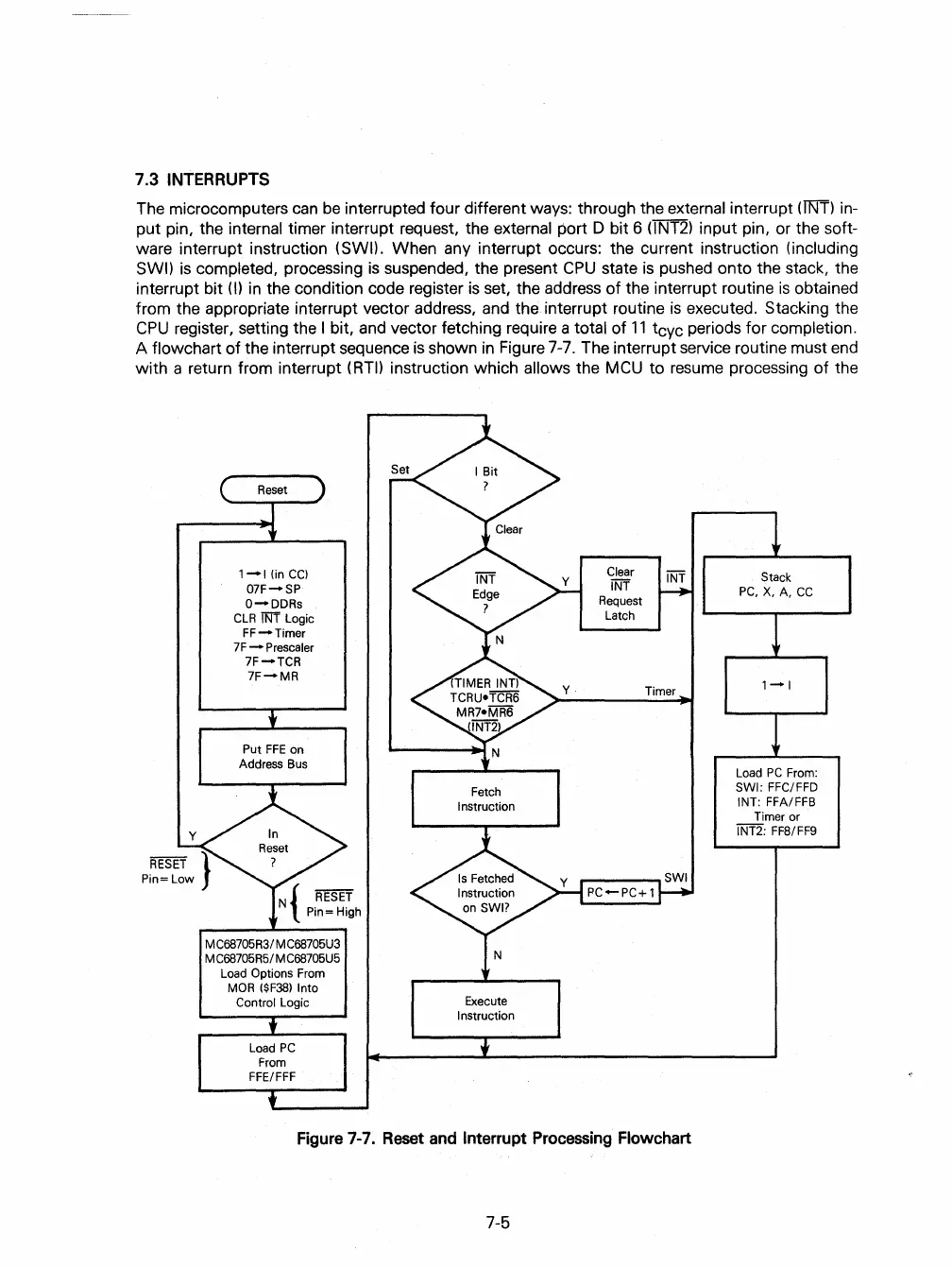
7.3
INTERRUPTS
The microcomputers
can
be
interrupted four different ways: through the external interrupt
(ll\ff)
in-
put pin, the internal timer interrupt request, the external
port D bit 6 (lNT2) input pin, or the soft-
ware interrupt instruction (SWI). When any interrupt occurs: the current instruction (including
SWI)
is
completed, processing
is
suspended, the present
CPU
state
is
pushed onto the stack, the
interrupt bit
(I) in the condition code register
is
set, the address of the interrupt routine
is
obtained
from the appropriate interrupt vector address,
and
the interrupt routine
is
executed. Stacking the
CPU
register, setting the I bit,
and
vector fetching require a total of
11
tcyc periods for completion.
A flowchart
of
the interrupt sequence
is
shown
in
Figure
7-7.
The interrupt service routine must
end
with a return from interrupt (RTI) instruction which allows the
MCU
to resume processing
of
the
1-1
(inCC)
07F-SP
O-DDRs
CLR
iNi Logic
FF-Timer
7F
- Prescaler
7F-TCR
7F-MR
Put
FFE
on
Address Bus
MC68705R3/ MC68705U3
M C68705R5/ MC68705U5
Load
Options From
MaR
($F38)
Into
Control
Logic
Load
PC
From
FFE/FFF
Fetch
Instruction
Execute
Instruction
Clear
INT
Request
Latch
Timer
Figure
7-7.
Reset
and
Interrupt
Processing
Flowchart
7-5
Stack
PC,X,A,CC
1-1
Load
PC
From:
SWI: FFC/FFD
INT: FFA/FFB
Timer or
INT2: FFS/FF9
 Loading...

